Solar cell

US20110265870A1Active Publication Date: 2011-11-03SHANGRAO JINKO SOLAR TECH DEV CO LTD

Image

  • Solar cell
  • Solar cell
  • Solar cell

Examples


first embodiment

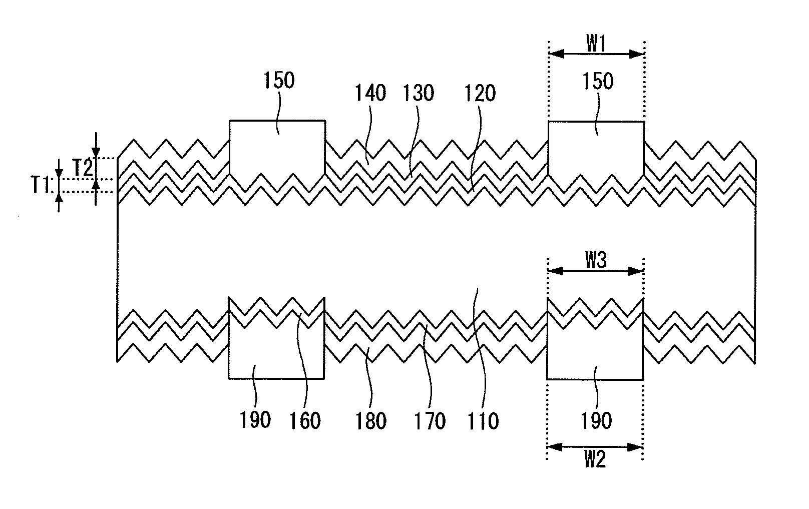
[0033]FIG. 1 is a schematic cross-sectional view of a solar cell according to the invention.

[0034]As shown in FIG. 1, a solar cell according to a first embodiment of the invention includes a substrate 110, an emitter layer 120 positioned at one surface of the substrate 110, for example, a front surface of the substrate 110, a first protective layer 130 positioned on the emitter layer 120, a first anti-reflection layer 140 positioned on the first protective layer 130, a plurality of first electrodes 150 positioned on the emitter layer 120 where the first protective layer 130 and the first anti-reflection layer 140 are not positioned, a back surface field (B SF) layer 160 positioned at a back surface of the substrate 110, a second protective layer 170 positioned on the back surface of the substrate 110, a second anti-reflection layer 180 positioned on a back surface of the second protective layer 170, and a plurality of second electrodes 190 positioned on a back surface of the back su...

second embodiment

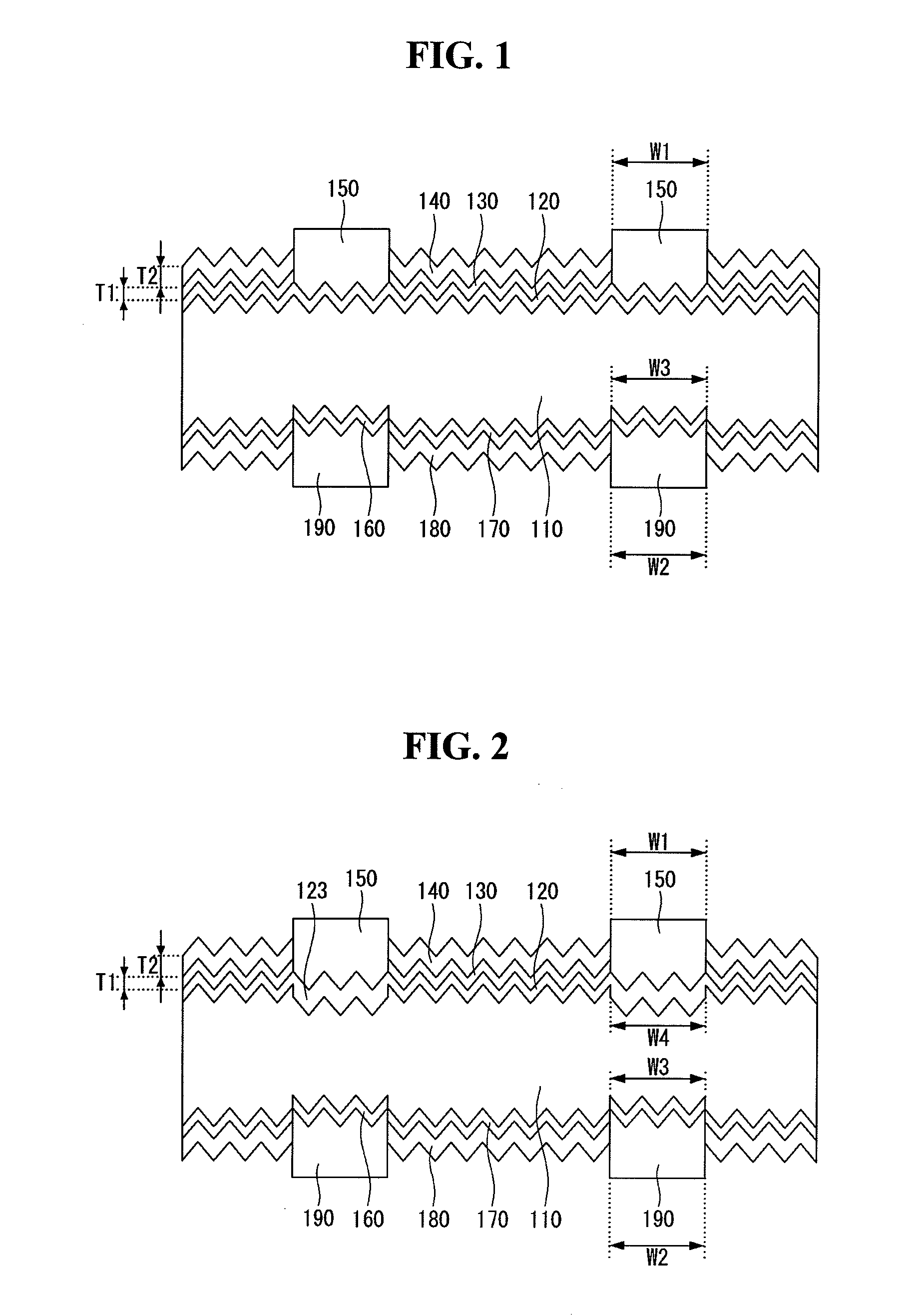
[0061]A solar cell according to the invention is described below with reference to FIG. 2.

[0062]Since the solar cell according to the second embodiment of the invention is substantially the same as the solar cell according to the first embodiment of the invention except an emitter layer, a further description may be briefly made or may be entirely omitted. Hereinafter, only a configuration of the emitter layer is described.

[0063]The emitter layer 120 according to the first embodiment of the invention has a uniform doping concentration throughout the entire area of the emitter layer 120. Thus, the emitter layer 120 according to the first embodiment of the invention may be easily manufactured through a simple process, but a recombination of carriers of the emitter layer 120 may increase because of a high doping concentration. As a result, an improvement in the efficiency of the solar cell may be limited.

[0064]Accordingly, the emitter layer 120 according to the second embodiment of the...


PUM


Abstract

A solar cell includes a substrate of a first conductive type, an emitter layer, of a second conductive type opposite the first conductive type, positioned at one surface of the substrate, a first electrode electrically connected to the emitter layer, a first protective layer positioned on a front surface of the emitter layer where the first electrode is not positioned, a back surface field layer positioned at another surface of the substrate, a second electrode electrically connected to the back surface field layer, and a second protective layer positioned on a back surface of the substrate where the second electrode is not positioned. Each of the first and second protective layers is formed of a material having fixed charges of the first conductive type.

Description

[0001]This application claims priority to and the benefit of Korean Patent Application No. 10-2011-0005429 filed in the Korean Intellectual Property Office on Jan. 19, 2011, the entire contents of which are incorporated herein by reference.BACKGROUND OF THE INVENTION[0002]1. Field of the Invention[0003]Embodiments of the invention relate to a solar cell.[0004]2. Description of the Related Art[0005]Solar power generation to convert light energy into electric energy using a photoelectric conversion effect has been widely used as a method for obtaining eco-friendly energy. A solar power generation system using a plurality of solar cell panels has been installed in places, such as houses due to an improvement in a photoelectric conversion efficiency of solar cells.[0006]The solar cell generally includes a substrate and an emitter layer that forms a p-n junction along with the substrate, thereby generating an electric current from light incident on the solar cell through one surface of t...

Claims


Application Information

Patent Timeline
03 Nov 2011
Publication
US20110265870A1
IPC
H01L31/0216; H01L31/0352
CPC
H01L31/02167; H01L31/02168; Y02E10/547; H01L31/1804; H01L31/068; Y02P70/50; H01L31/02363; H01L31/022425
Inventors
PARK, CHANGSEO; JIN, YOONSIL