Fe-BASED SOFT MAGNETIC ALLOY AND DUST CORE USING Fe-BASED SOFT MAGNETIC ALLOY
Active Publication Date: 2011-11-03
ALPS ALPINE CO LTD
View PDF9 Cites 10 Cited by
Summary
Abstract
Description
Claims
Application Information
AI Technical Summary
This helps you quickly interpret patents by identifying the three key elements:
Problems solved by technology
Method used
Benefits of technology
Benefits of technology
[0009]The invention provides an Fe-based soft magnetic alloy capable of obtaining a low core loss and high DC-superposed characteristics, and a dust core using the Fe-based soft magnetic alloy.
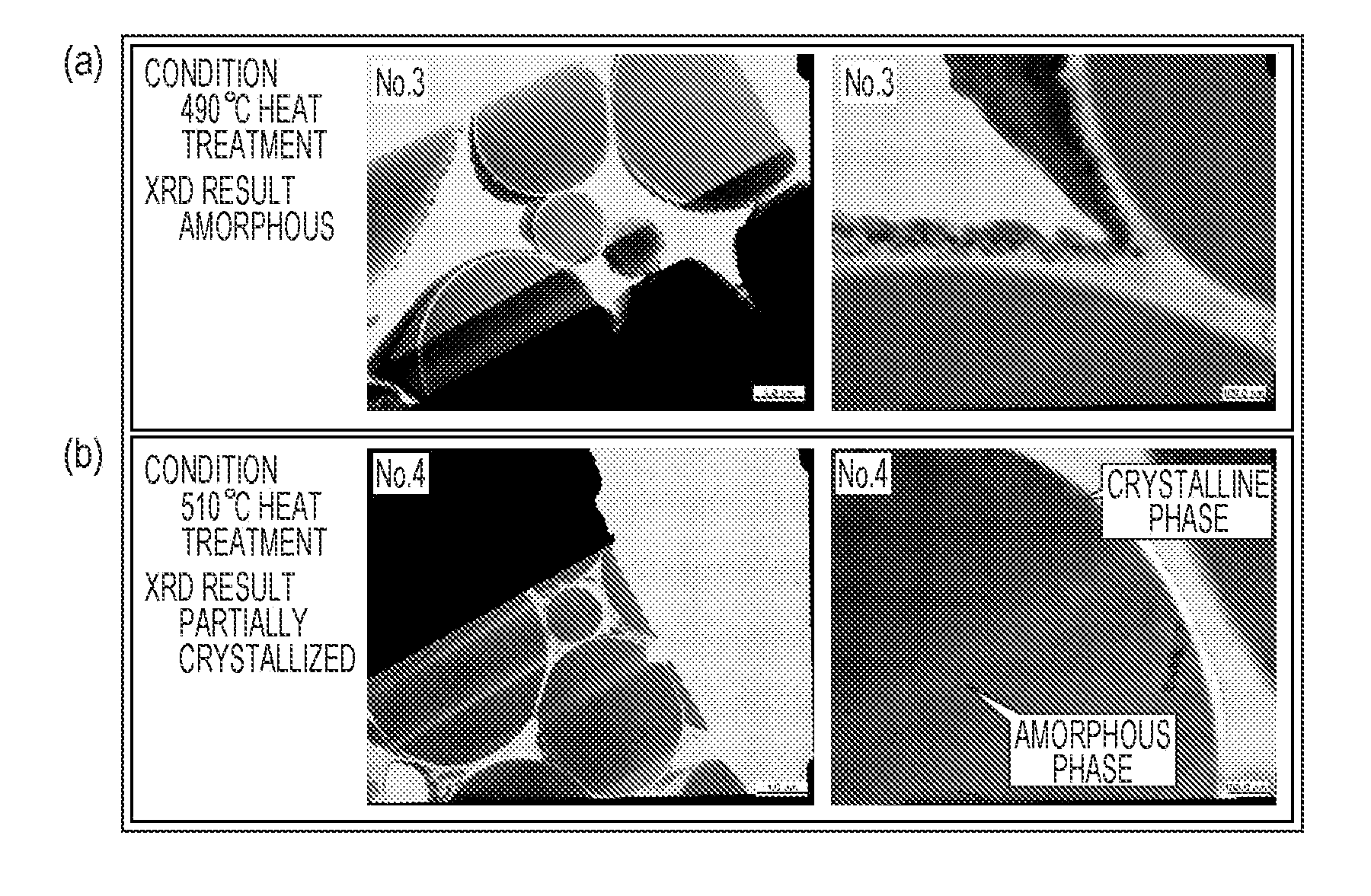
[0017]According to the aspect of the invention, the Fe-based soft magnetic alloy that is obtained by an atomizing method, a liquid quenching method, or the like is subjected to a predetermined heating treatment to precipitate the α-Fe crystal phase, thereby obtaining the mixed-phase structure in which the amorphous phase and the α-Fe crystal phase are mixed. When an Fe-based soft magnetic alloy that deviates from the above composition is subjected to a heating treatment, an Fe compound is precipitated without precipitation of the α-Fe crystal phase, or the precipitation temperature of the α-Fe crystal phase and the precipitation temperature of the Fe compound become too close to each other, and the Fe compound is more likely to be precipitated as well as the α-Fe crystal phase. In the Fe-based soft magnetic alloy according to the aspect of the invention, temperature management can be properly performed during a heat treatment so that a temperature difference of equal to or greater than 20° between the precipitation temperature of α-Fe and the precipitation temperature of the Fe compound is provided.
[0019]According to the aspect of the invention, the diameter of the crystallite of the α-Fe crystal phase included in the mixed-phase structure is controlled to be equal to or smaller than 50 nm, and the volume fraction of the α-Fe crystal phase to the total is controlled to be equal to or lower than 40%, so that the core loss can be reduced efficiently.
[0020]In addition, as the Fe-based soft magnetic alloy according to the aspect of the invention is applied to the dust core, increases in frequency, current, and the like can be properly coped with.
[0022]In addition, as the Fe-based soft magnetic alloy according to the aspect of the invention is applied to the dust core, increases in frequency, current, and the like can be properly coped with.
Problems solved by technology
However, this alloy base has insufficient amorphous forming ability, and since the cooling rate thereof is insufficient when a general water atomizing method or gas atomizing method is used as a method of forming a powder alloy, homogeneous and complete amorphous alloy powder cannot be made.
Therefore, a homogenous bcc Fe(α-Fe) crystal phase cannot be obtained even though a crystallization heat treatment is performed thereafter, and a compound phase is precipitated.
Therefore, there is a disadvantage that magnetic characteristics are significantly deteriorated when a dust core is formed of the powder.
Method used
Image
Click on the blue label to locate the original text in one second.
Reading with bidirectional positioning of images and text.
Examples
examples
Experiment on Composition Range
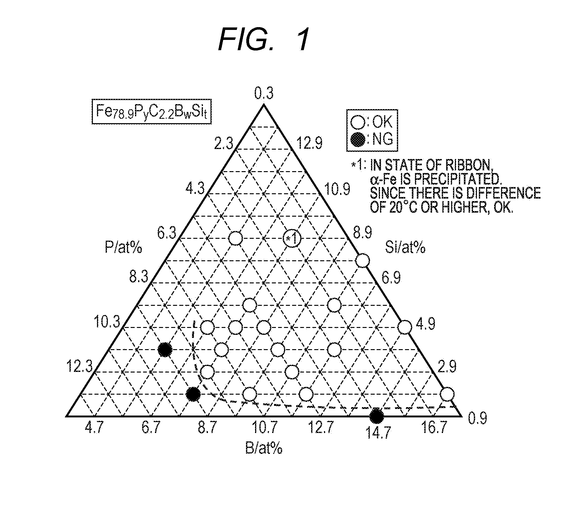
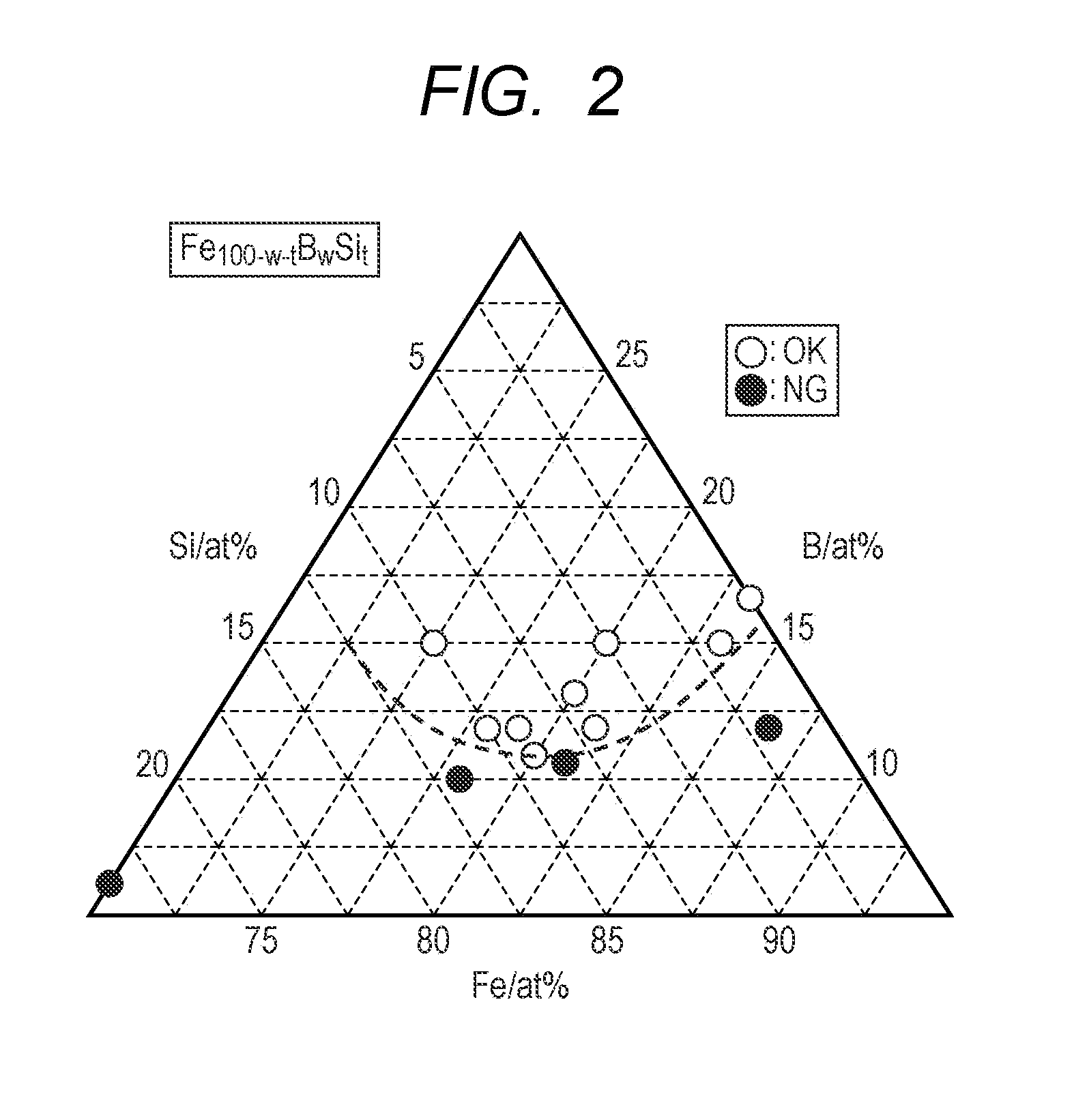
[0095]A large number of Fe-based soft magnetic alloys shown in Table 1 (in Appendix) were formed. The alloys were all formed into ribbon shapes by a liquid quenching method.
[0096]In Table 1, Tc, Tg, Tx, ΔTx, Tm, Tg / Tm, Tx / Tm, and saturation magnetization σs of each sample are described.
[0097]Moreover, in precipitation temperature fields shown in Table 1, the precipitation temperatures of α-Fe crystal phases and the precipitation temperatures of Fe compounds are described. In addition, the mark “O” represents that an α-Fe crystal phase is precipitated when a heating treatment is performed at a rate of temperature increase of 40° C. / min, and there is a temperature difference of equal to or greater than 20° C. between the precipitation temperature of the α-Fe crystal phase and the precipitation temperature of the Fe compound. For each sample, a heat treatment temperature was gradually increased, and temperatures at which the α-Fe crystal phase and the Fe ...
example
[0149]Next, an Fe-based soft magnetic alloy of No. 48 in Table 1 was formed into a ribbon form by a liquid quenching method, and the Fe-based soft magnetic alloy was formed into a powder form by a water atomizing method. Powder characteristics are shown in Table 6 as follows.
[0150]Moreover, the Fe-based soft magnetic alloy in the powder form shown in Table 6 was not subjected to the heating treatment.
[0151]Subsequently, a dust core was formed using the Fe-based soft magnetic alloy powder shown in Table 6.
[0152]The Fe-based soft magnetic alloy powder shown in Table 6, silicone resin (1.4 mass %), and zincstearate (0.3 mass %) were mixed, dried, and ground, the resultant was sifted to 300 to 850 μm using a sifter having an opening of 300 μm and an opening of 850 μm so as to form granulated powder, the granulated powder was formed into a core precursor having a rin...
PUM
Property
Measurement
Unit
Temperature
aaaaa
aaaaa
Fraction
aaaaa
aaaaa
Nanoscale particle size
aaaaa
aaaaa
Abstract
An Fe-based soft magnetic alloy includes: Fe; and a component R, wherein the component R contains at least one of P, C, B, and Si, there is a temperature difference of equal to or greater than 20° C. between a precipitation temperature of an α-Fe crystal phase and a precipitation temperature of an Fe compound, the Fe-based soft magnetic alloy is formed of a mixed-phase structure in which an amorphous phase and the α-Fe crystal phase are mixed, and a diameter of a crystallite of the α-Fe crystal phase is equal to or smaller than 50 nm, and a volume fraction of the α-Fe crystal phase to the total is equal to or lower than 40%. In addition, the composition formula is represented by Fe100-x-uJxRu, a component J contains at least one of Cr, Co, Ni, and Nb, and 0 at %≦x≦6 at %, 17 at %≦u≦25 at %, and 17 at %≦x+u≦27.1 at % are satisfied.
Description
CLAIM OF PRIORITY[0001]This application is a Continuation of International Application No. PCT / JP2010 / 050673 filed on Jan. 21, 2010, which claims benefit of Japanese Patent Application No. 2009-012542 filed on Jan. 23, 2009. The entire contents of each application noted above are hereby incorporated by reference.BACKGROUND OF THE INVENTION[0002]1. Field of the Invention[0003]The present invention relates to an Fe-based soft magnetic alloy applied to a magnetic core (dust core) of a transformer or a choke coil for a power supply.[0004]2. Description of the Related Art[0005]Dust cores using Fe metallic powder, Fe—Ni alloypowder, Fe—Al—Si alloypowder, or the like which are applied to electronic components and the like require a low core loss and excellent DC-superposed characteristics due to increases in frequency and current in recent years.[0006]The dust cores are formed by solidifying soft magnetic alloy powder into a desired shape using a binding material and therefore have a low...
Claims
Application Information
Patent Timeline
Application Date:The date an application was filed.
Publication Date:The date a patent or application was officially published.
First Publication Date:The earliest publication date of a patent with the same application number.
Issue Date:Publication date of the patent grant document.
PCT Entry Date:The Entry date of PCT National Phase.
Estimated Expiry Date:The statutory expiry date of a patent right according to the Patent Law, and it is the longest term of protection that the patent right can achieve without the termination of the patent right due to other reasons(Term extension factor has been taken into account ).
Invalid Date:Actual expiry date is based on effective date or publication date of legal transaction data of invalid patent.

