
Dye sensitized solar cell

Inactive Publication Date: 2011-11-10
ELECTRONICS & TELECOMM RES INST
View PDF4 Cites 3 Cited by
  • Summary
  • Abstract
  • Description
  • Claims
  • Application Information

AI Technical Summary

Benefits of technology

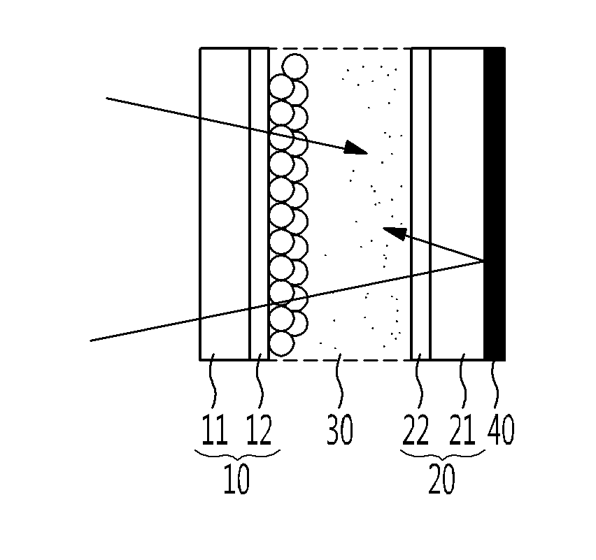
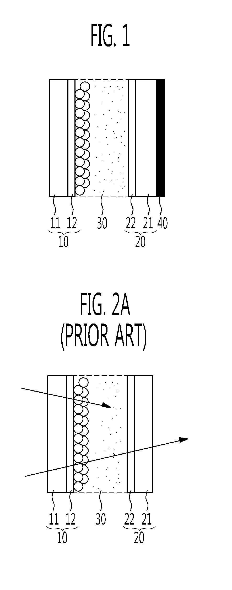
[0011]The present invention is directed to provide a dye-sensitized solar cell (DSC) whose photoelectric conversion efficiency is improved by employing a polymer film having an excellent mirror reflection characteristic and flexibility.
[0016]The polymer film having a mirror reflection characteristic may be attached to the rear side of the counter electrode avoiding any scratch on the surface of the polymeric mirror.

Problems solved by technology

However, silicon solar cells require relatively high production cost owing to the use of silicon material which is also widely used in semiconductors production.
However, conventional methods showed limitation in improving the photoelectric conversion efficiency of a solar cell, and new technology is required to improve the efficiency.

Method used


Image

  • Dye sensitized solar cell
  • Dye sensitized solar cell
  • Dye sensitized solar cell

Examples


exemplary embodiment 1

(1) Fabrication of Working Electrode

[0041]After conductive glass coated with fluorine-doped tin oxide (FTO) (Pilkington, TEC 7) was cut off in a size of 1.5 cm×1.5 cm and underwent ultrasonic cleaning with soapy water for five minutes, the soapy water was completely removed. After this, ultrasonic cleaning with ethanol was repeated three times for five minutes. Subsequently, the FTO glass was completely rinsed with absolute ethanol and then dried in an oven. To increase adhesion to TiO2, the resultant FTO glass was spin-coated with 0.2 M titanium (IV) butoxide solution and completely dried in an oven. The resultant FTO glass was coated with titania using a Dr. Blade and then dried at 100° C. for ten minutes. After this, the resultant FTO glass was annealed at 450° C. to obtain a TiO2 film having a thickness of 10 μm. The electrode fabricated in this way was put in a dye solution mixed with absolute ethanol at a concentration of 0.5 mM and left for 24 hours to absorb dye. In this emb...

exemplary embodiment 2

[0045]A DSC was manufactured to be the same as Exemplary embodiment 1 except that a polymer film having a mirror reflection characteristic was attached to the outside of a counter electrode in a size of 1.5 cm×1.5 cm (width×length) (i.e., attached to an entire surface of the counter electrode), which is larger than an active area.

experimental example

Energy Conversion Efficiency

[0048]The DSCs manufactured according to Exemplary Embodiments 1 and 2 and Comparative Examples 1 and 2 were illuminated by a Xe lamp (Oriel, 300 W Xe arc lamp) with an AM 1.5 solar simulating filter, and a current-voltage curve was obtained using an M236 source measure unit (SMU, Keithley). Electric potential had a range from −0.8 V to 0.2 V, and light had intensity of 100 mW / cm2. In this way, energy conversion efficiency was measured. Fill factors were calculated using the conversion efficiency and a formula below, and the results are shown in Table 1.

Fill factor (%)=((J×V)max / (Jsc×Voc))×100  Formula

[0049]In the formula above, J denotes a Y-axis value of the conversion efficiency curve, V denotes an X-axis value of the conversion efficiency curve, and Jsc and Voc are intercepts of the respective axes.

TABLE 1ExemplaryExemplaryEmbodimentEmbodimentComparativeComparative12Example 1Example 2Energy7.89.97.07.5ConversionEfficiency (%)Increase in11.141.407.1Eff...


PUM


Abstract

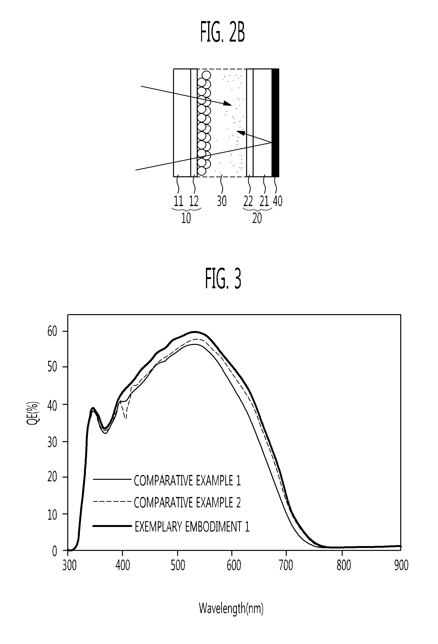
Provided is a dye-sensitized solar cell (DSC). The DSC including a working electrode and a counter electrode facing the working electrode includes a polymer film having a mirror reflection characteristic and attached to the outside of the counter electrode. Since the polymer film having a mirror reflection characteristic is employed, use of light can be increased, and incident photon-to-current conversion efficiency (IPCE) can be improved.

Description

CROSS-REFERENCE TO RELATED APPLICATION[0001]This application claims priority to and the benefit of Korean Patent Application No. 10-2010-0042569, filed May 6, 2010, the disclosure of which is incorporated herein by reference in its entirety.BACKGROUND[0002]1. Field of the Invention[0003]The present invention relates to a dye-sensitized solar cell (DSC), and more particularly to a DSC in which a polymer film having a mirror reflection characteristic is attached to the rear side of a counter electrode to improve power conversion efficiency.[0004]2. Discussion of Related Art[0005]Lately, various kinds of energies for replacing fossil fuels have been researched in order to reduce the amount of carbon dioxide, which is regarded as the main culprit of global warming, and solve the emerging problem of energy. In particular, research for making use of natural energies such as wind power, nuclear power, and sunlight is extensively under way. Among these natural energies, a solar cell using s...

Claims


Application Information

Patent Timeline
IPC IPC(8): H01L31/0232H01L31/0224
CPCH01G9/2031H01G9/2059Y02E10/542H01G9/209H01G9/2068Y02P70/50
Inventor LEE, YOUNG GIKIM, KWANG MANCHO, KUK YOUNGPARK, JUNG KILEE, SEUNG WOOJUN, YONG SEOK
Owner ELECTRONICS & TELECOMM RES INST
Learn More