Variable Compliance Wheel

Active Publication Date: 2011-11-10
MILLENWORKS
View PDF0 Cites 59 Cited by
  • Summary
  • Abstract
  • Description
  • Claims
  • Application Information

AI Technical Summary

Benefits of technology

[0011]Multiple inner and outer wheel segments can be stacked to produce a wheel with varying radial stiffness across the width of the wheel. This is beneficial for improving the lateral performance of the wheel by controlling the wheel's dynamic camber. In the example of wheels supporting a conveyer belt, this varying stiffness across the wheel width may help direct or steer baggage in a desired direction. In the example of a printer, the varying radial stiffness of a printer roller may direct paper in a desired direction or area, such as continuously adjusting the registration of multicolor press runs. This reduces the waste and rework associated with misregistered press output.
[0012]In the example of the vehicle, the dynamic camber can adjusted during cornering to improve maneuvering performance. This can also be beneficial for changing the heading of the vehicle while driving with little or no steeri

Problems solved by technology

The shortcomings of this design are complexity, sensitivity to the elements, cost, and i

Method used


Image

  • Variable Compliance Wheel
  • Variable Compliance Wheel
  • Variable Compliance Wheel

Examples


Embodiment Construction

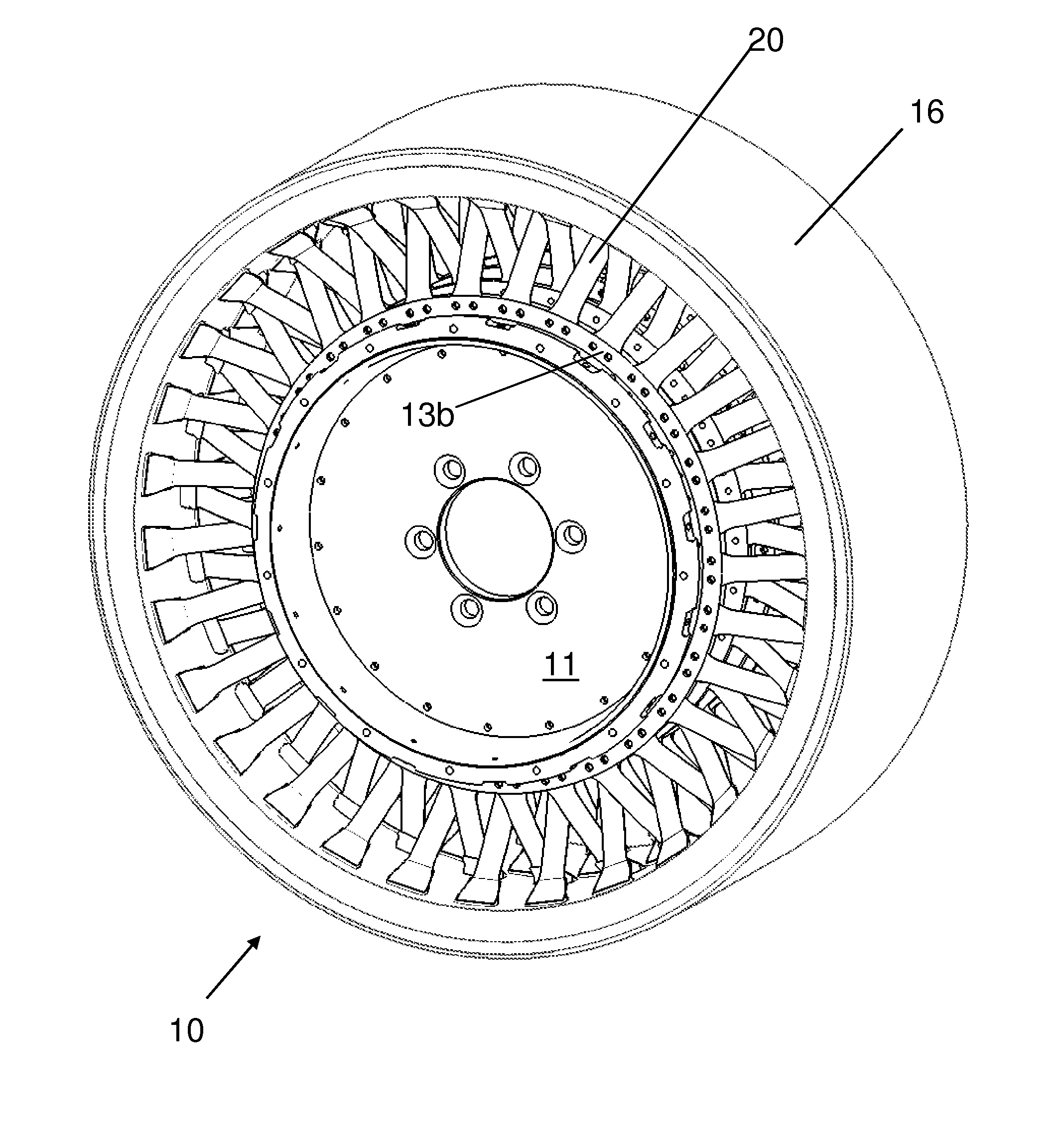
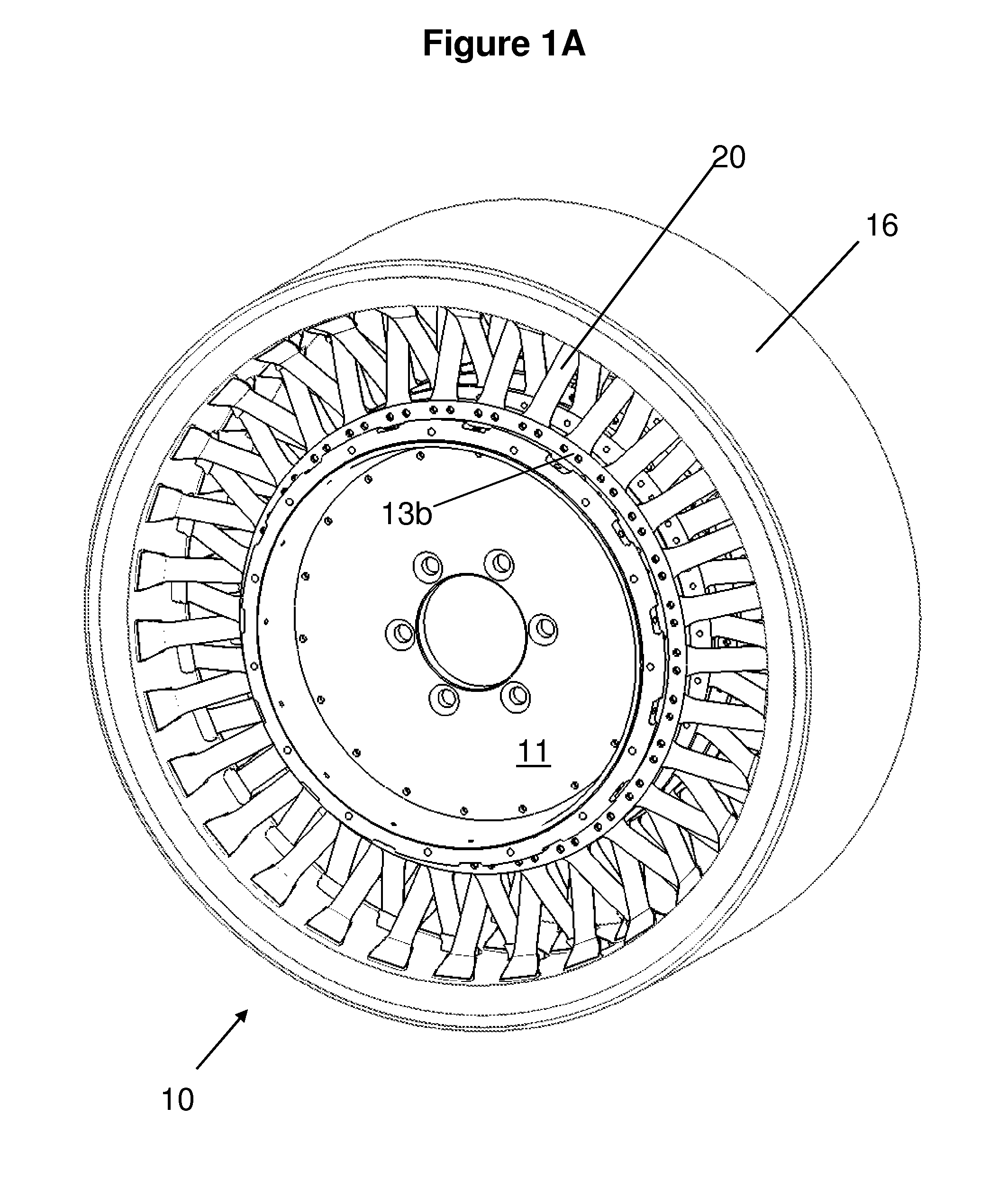
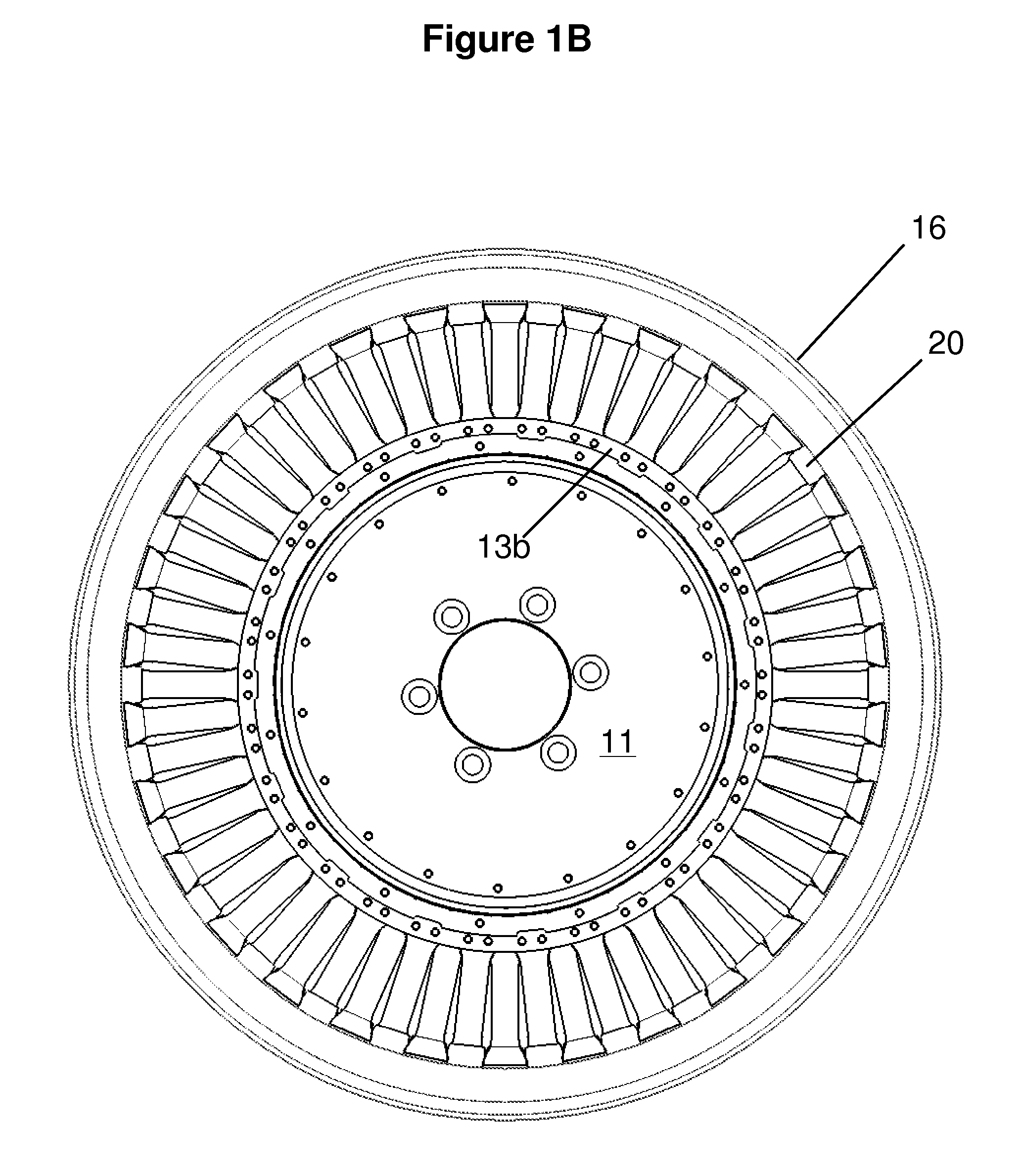
[0030]FIGS. 1A, 1B, 2, and 3 illustrate a first preferred embodiment of a variable stiffness wheel 10. The variable stiffness wheel 10 includes a hub 11, fixed flanges 12b and 13b and movable flanges 12a and 13a (also referred to as rings, plates and collars in this specification), and a plurality of wheel segments 17, 18 (e.g., two oppositely angled spokes 20) engaged with the flanges 12a, 12b, 13a, 13b and an outer traction element 16.

[0031]The hub 11 includes an inner flange (not shown) which locates an adaptor plate and thereby allows the wheel 10 to be mounted on a spindle (not shown) which allows the variable stiffness wheel to rotate about the center axis. Preferably the spindle and mounting mechanism is similar to wheel mounting mechanism of present vehicles (e.g., secured by lug nuts). While the variable stiffness wheel 10, as well as other embodiments of the present invention, are described as being used on a vehicle, it should be understood that these embodiments can be u...


PUM


Abstract

A system for adjusting the compliance of a wheel is provided. In one embodiment, wheel segments are adjusted, causing the stiffness of the wheel to change. Such adjustments can be made while the wheel is rotating, allowing the wheel compliance to be changed while a vehicle is in motion.

Description

RELATED APPLICATIONS[0001]This application is a continuation-in-part of International Patent Application No. PCT / US05 / 15478, International Filing Date Jun. 13, 2005, entitled Variable Radial And / Or Lateral Compliance Wheel; and claims priority to U.S. Provisional Application Ser. No. 60 / 869,714 filed Dec. 12, 2006 entitled Variable Compliance Wheel, both of which are hereby incorporated by reference.BACKGROUND OF THE INVENTION[0002]The present invention generally relates to a wheel with variable compliance having many applications, including ground vehicle wheels, printing press rollers, material processing and handling equipment. More particularly, the present invention relates to a wheel that includes a hub having a center axis of rotation and a plurality of wheel segments engaged with the hub and connecting to a radial band appropriate for the intended usage of the wheel, where the hub and plurality of wheel segments are adapted to rotate about the center axis, and where the atta...

Claims


Application Information

Patent Timeline
IPC IPC(8): B60B1/02F16C13/00B65G13/02
CPCB60B9/26B60B9/04B60C19/00B60C7/18B60C7/14
Inventor ANDERFAAS, ERICMILLER, BRIANBANKS, DEANCHARLAND, JONCLEMENS, DAVIDCULBERTSON, CHRISLENOACH, PETERTRAUERNICHT, JARED
Owner MILLENWORKS
Why Eureka
Try Eureka