[0005]It is the object of the present invention to provide an X-ray imaging system which not only enables
good image quality in respect of spatial resolution but also allows good
visualization of
soft tissue.
[0007]The biplane X-ray imaging system according to the invention has two recording units arranged in different planes, each such unit having an X-ray
detector and an X-ray source, wherein the first recording unit is formed by a phase-contrast recording unit for phase-contrast X-ray imaging. Phase-contrast X-ray imaging exploits the fact that different types of
body tissue diffract X-ray beams to different degrees. The phase shift effect when an X-ray beams passes through an examination subject is significantly stronger than the
absorption effect of the material penetrated by the X-
ray radiation. By means of phase-contrast X-ray imaging soft parts can be represented with particularly
high contrast in X-ray examinations. In combination with a second, conventional recording unit (which measures the X-
ray radiation attenuated through absorption in an examination subject) the biplane X-ray imaging system according to the invention can provide not only conventional projection images but also particularly high-quality visualizations of soft parts. This makes such a system also suitable for minimally invasive interventions and minimally surgical interventional procedures.
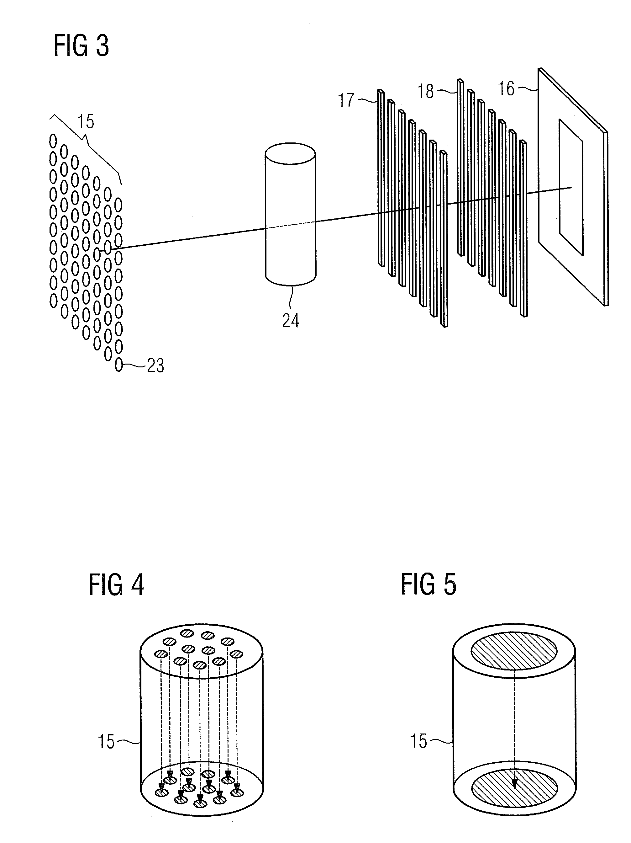
[0008]According to an embodiment of the invention the first recording unit embodied for phase-contrast X-ray imaging has an X-ray tube
assembly, an X-ray detector, a
phase grating which is disposed between an examination subject and the X-ray detector, and an amplitude
grating which is disposed between the
phase grating and the X-ray detector. In order to generate quasi-coherent X-
ray radiation, as is required for phase-contrast X-ray imaging, two alternatives can be used: According to a first alternative the first recording unit has a further
grating which is disposed behind the X-ray tube
assembly of the first recording unit and is embodied for the purpose of generating coherent X-ray
radiation from the non-coherent X-ray
radiation of the X-ray tube
assembly. According to a second alternative the X-ray tube assembly of the first recording unit has a plurality of field-emission X-ray sources for emitting quasi-coherent X-ray
radiation. Integrating an X-ray tube assembly having field-emission X-ray sources into a phase-contrast X-ray imaging system eliminates the need for the complex source
grating for generating monochromatic X-ray radiation, because the field-emission X-ray sources constitute a simple and effortless means of generating mutually coherent X-ray beams with a narrow focus. This enables the X-ray imaging system to be manufactured in a particularly compact design and particularly economically.
[0012]In the case of a field-emission X-ray source or, as the case may be, the corresponding field-emission
cathode, electrons are emitted as a result of a sufficiently high
electric field being applied. Field emission is achieved e.g. by means of a simple
diode mode in which a bias
voltage is applied between
anode and
cathode. Electrons are emitted by the
cathode when the
electric field exceeds the emission threshold. A
triode construction can also be provided in which a gate
electrode is disposed close to the cathode. Electrons are emitted here by applying a bias
voltage between gate and cathode. The emitted electrons are then accelerated by means of a
high voltage between gate and
anode. Field-emission cathodes a very high, readily controllable and easily focusable
electron beam current. All in all, by means of the field-emission X-ray sources the invention affords the advantages of low
heat generation by the field-emission X-ray tube assembly and a low weight, not only on account of the field-emission tube assembly itself but also as a result of the omission or reduction in size of a cooling system. Furthermore such a field-emission tube assembly is highly compact in comparison with conventional X-ray tube assemblies, thereby establishing the
precondition for providing a high-quality, laminar X-ray source having a surface area of many focal points arranged adjacent to one another. This is ensured in particular by means of an array having a plurality of field-emission tube assemblies. The useful life of field-emission tube assemblies is also significantly higher than that of known X-ray tube assemblies using thermal cathodes. In addition, by comparison with a thermal cathode a field-emission cathode can be started quickly without heating. Moreover, a higher spatial resolution can be achieved for X-ray images thanks to the readily focusable
electron current.
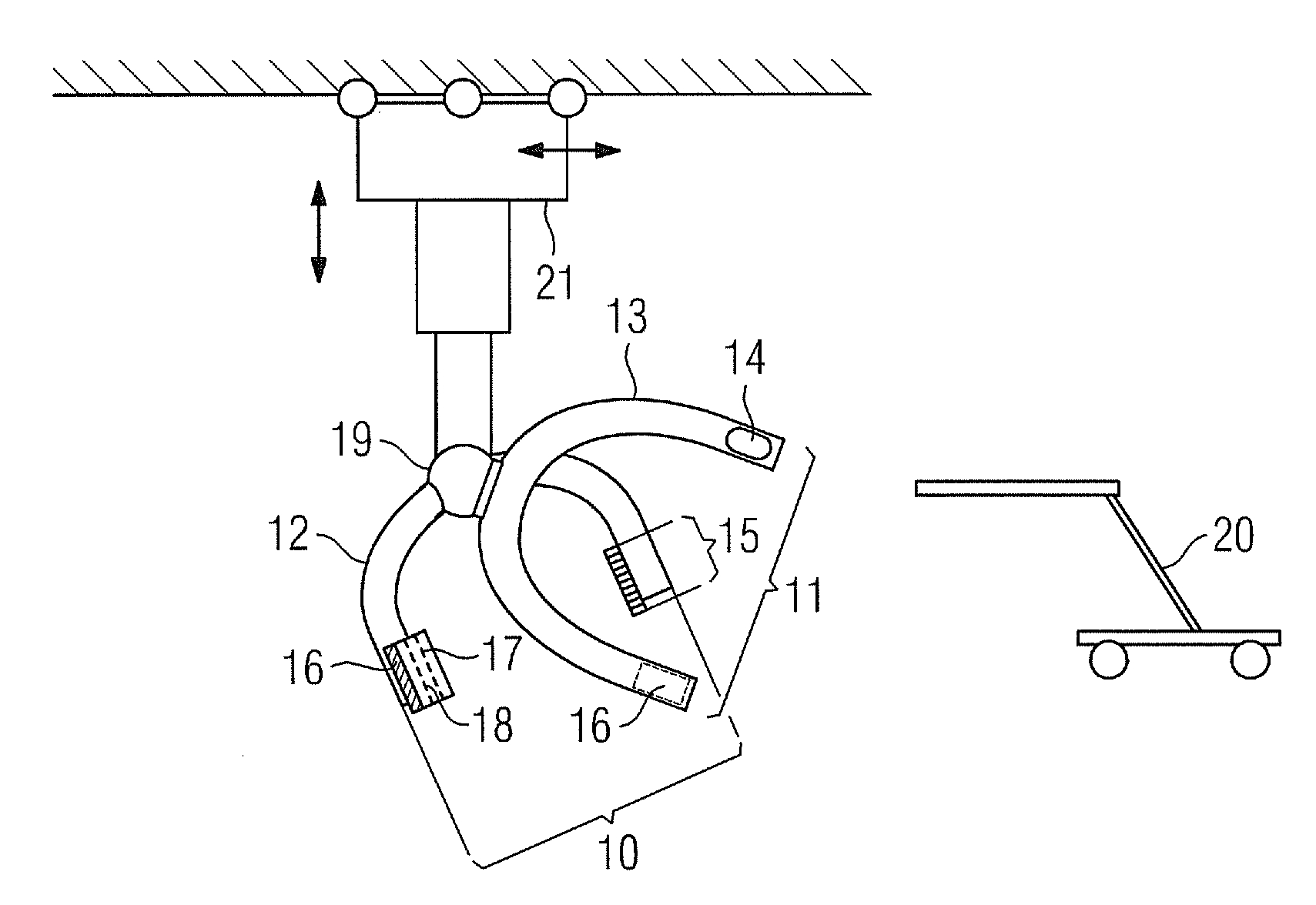
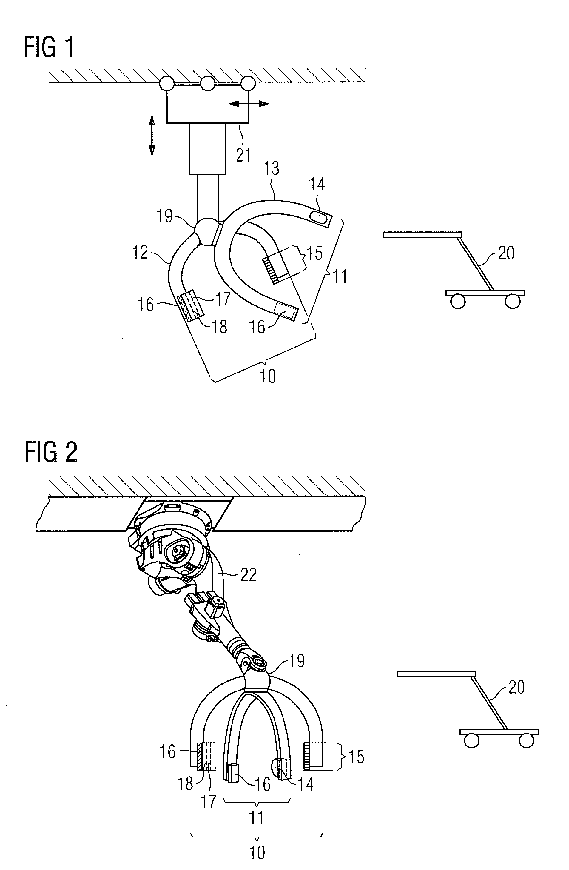
[0018]Both recording units beneficially have C-arms. The recording units are advantageously disposed on at least one
robotic arm, in particular a 6-axis articulated-arm
robot, in order to provide particularly good, quick and simple adjustability in three dimensions.

