
Removal of trapped silicon with a cleaning gas

a technology of cleaning gas and silicon, applied in the direction of separation processes, machines/engines, mechanical equipment, etc., can solve the problems of clogging the vacuum pump, causing a violent reaction and even an explosion, and affecting the effect of vacuum pump operation, so as to prevent the build-up of explosive materials

Inactive Publication Date: 2011-11-10
APPLIED MATERIALS INC
View PDF0 Cites 2 Cited by
  • Summary
  • Abstract
  • Description
  • Claims
  • Application Information

AI Technical Summary

Benefits of technology

[0007]The present invention generally relates to an apparatus and method of managing particles and material accumulation in exhaust components used in deposition systems. More specifically, embodiments of the present invention relate to an apparatus and method of preventing build-up of explosive material in vacuum forelines of chemical vapor deposition systems.

Problems solved by technology

If the highly reactive dust or particulate is subsequently exposed to air, such as during maintenance, there can be a violent reaction and even an explosion.
Moreover, in some cases, the silicon-containing particulates may travel downstream and clog the vacuum pumps.
However, microcrystalline silicon deposition processes generate more powder than can effectively be etched away in a cleaning step.
Another drawback to cleaning the foreline with an etchant is that it is difficult to determine how far down the foreline the silicon is etched and removed.
Furthermore, the lines may get hot from the etching process, leading to a potentially explosive situation if unreacted powder remains in the foreline.
This solution, however, may not comport with environmental regulations.
However, after many deposition cycles, the catch pot gets full and needs to be emptied out.
Emptying out the catch pot is a dangerous procedure because the powder collected is very fine and is highly reactive, which can lead to explosions and the generation of significant amounts of heat as the highly reactive powder is oxidized.
Moreover, the catch pot needs to emptied from time to time, which leads to process down time.

Method used


Image

  • Removal of trapped silicon with a cleaning gas
  • Removal of trapped silicon with a cleaning gas
  • Removal of trapped silicon with a cleaning gas

Examples


Embodiment Construction

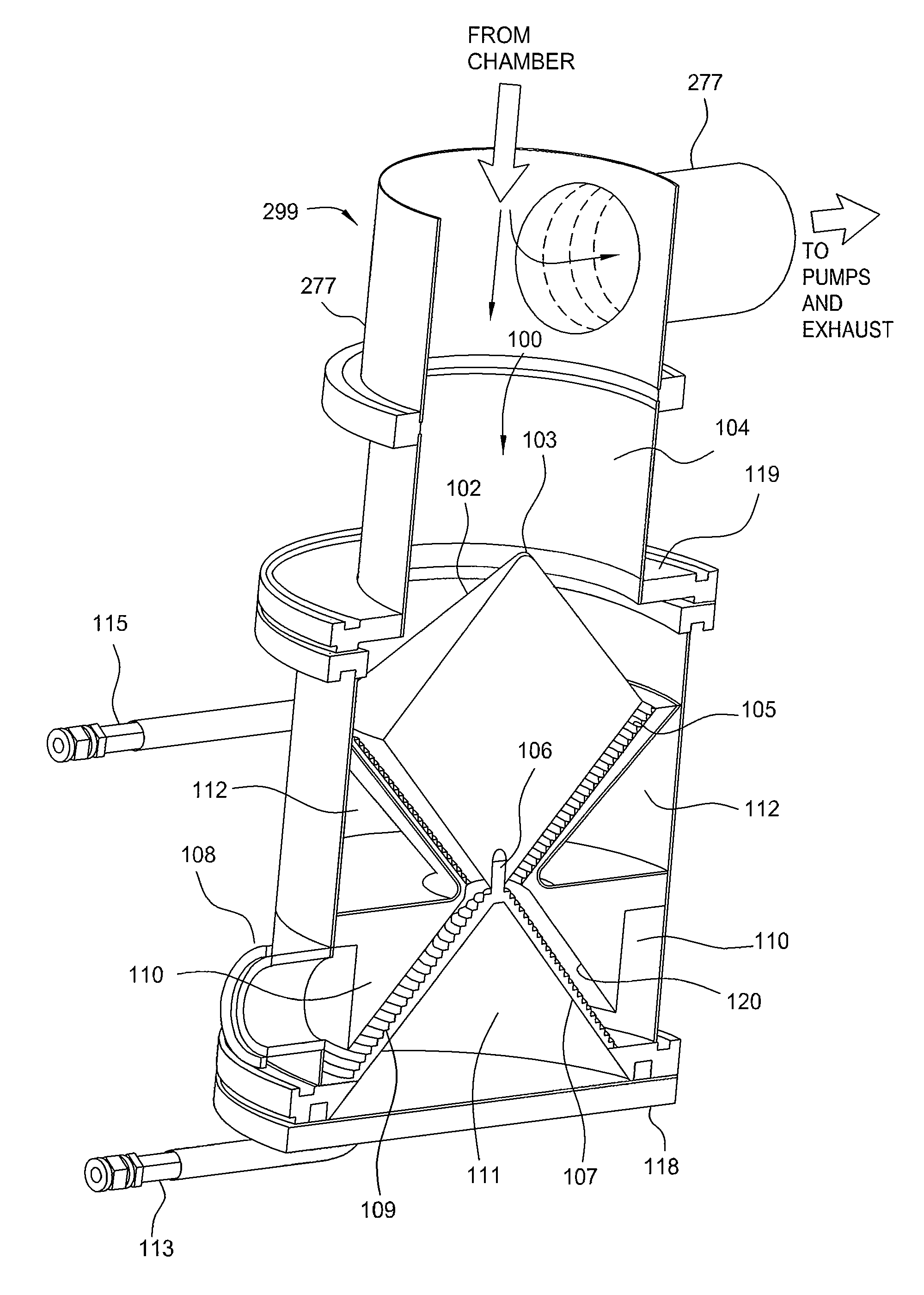
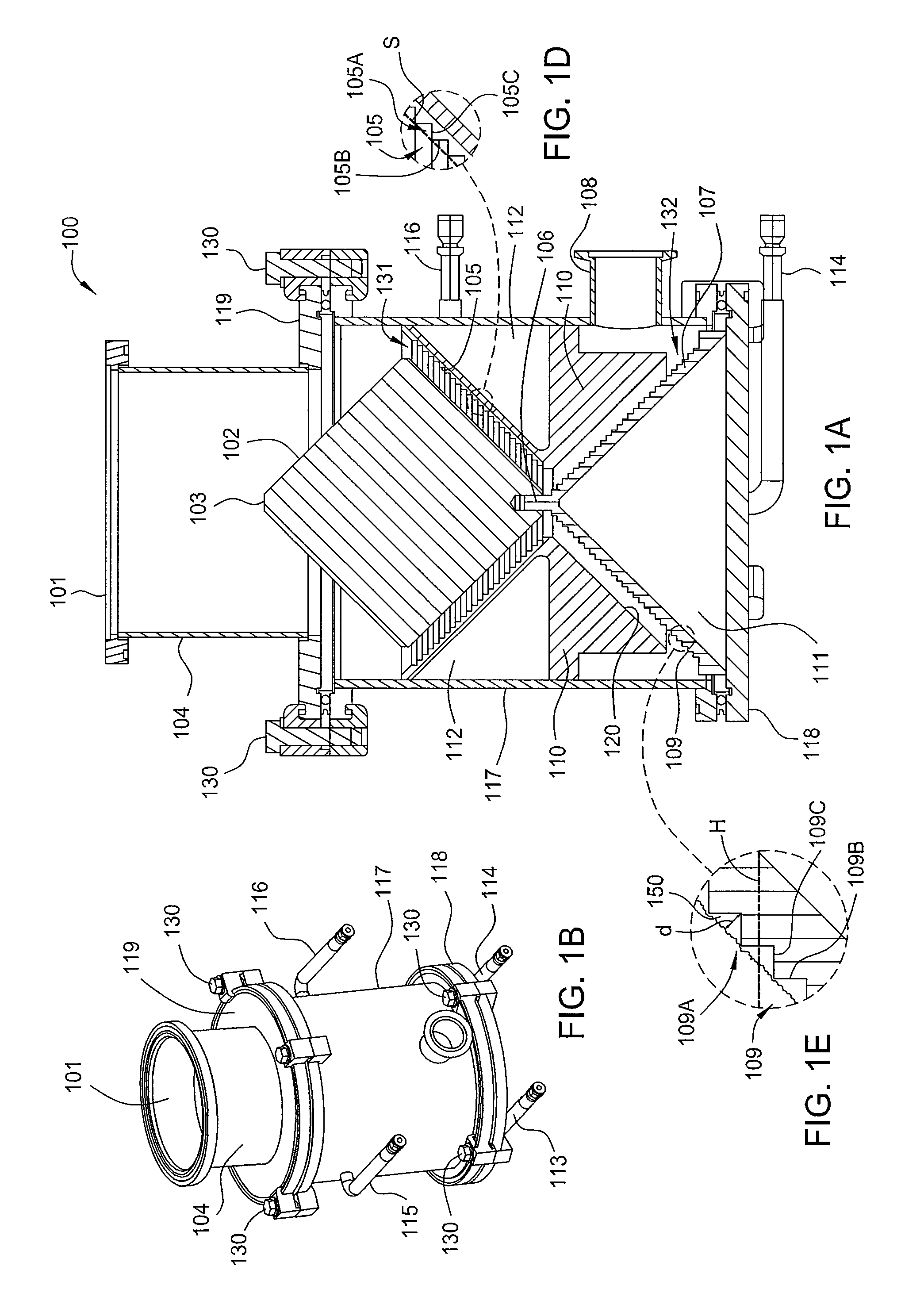
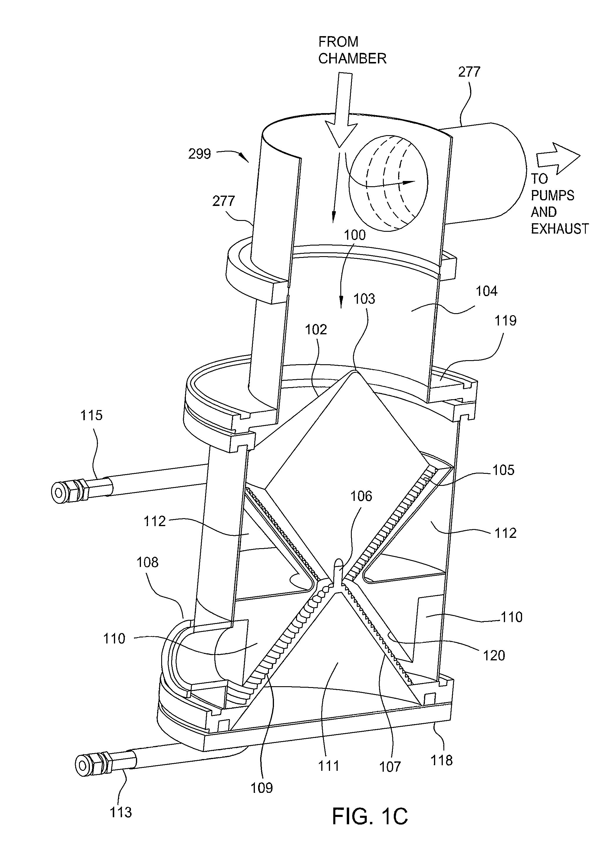
[0019]Embodiments described herein provide a method and apparatus for cleaning exhaust components found in a vacuum deposition system, such as particulate collection devices, including catchpots connected to vacuum forelines in a deposition system, such as a chemical vapor deposition system. More specifically, embodiments of the present invention relate to a method and apparatus of preventing build-up of a highly reactive material in catchpots coupled to a vacuum foreline connected to a chemical vapor deposition system. In one embodiment, a catchpot is provided having an interior surface area which maximizes the rate of reaction between silicon particulates landing on the interior surface area of the catchpot and nitrogen trifluoride flowing through the catchpot.

[0020]FIG. 1A illustrates a cross-sectional view of one embodiment of a catchpot 100 having a collection region comprising an upper interior reaction surface area 131 generally resembling an inverted cone and a lower reactio...


PUM

PropertyMeasurementUnit
Angleaaaaaaaaaa
Angleaaaaaaaaaa
Frequencyaaaaaaaaaa

Abstract

Embodiments of the present invention relate to apparatus and methods of preventing build-up of explosive material in vacuum forelines of deposition systems. A cleaning gas such as nitrogen trifluoride (NF3) may be introduced into a particulate collection device including a catchpot having a configuration comprising a sloped interior surface area that maximizes the amount of reactive silicon-containing particles that are exposed to and react with the cleaning gas stream to form silicon tetrafluoride (SiF4) and other non-reactive by-products. The degree of slope of the interior surface area may be based upon the angle of repose of the silicon-containing particles. The gaseous silicon tetrafluoride (SiF4) and other non-reactive by-products can flow out of the catchpot and into the exhaust stream towards a vacuum pump. The apparatus and method may also avoid accumulation of highly reactive and highly explosive particulates in catchpots.

Description

BACKGROUND OF THE INVENTION[0001]1. Field of the Invention[0002]Embodiments of the present invention generally relate to an apparatus and method of managing particles and material accumulation in exhaust components used in deposition systems. More specifically, embodiments of the present invention relate to an apparatus and method of preventing build-up of explosive material in vacuum forelines of chemical vapor deposition systems.[0003]2. Description of the Related Art[0004]Typically, chemical vapor deposition (CVD), atomic layer deposition (ALD) and other vapor phase deposition process will generate highly reactive silicon powder by-products. These by-products may comprise primarily silicon (Si), but other silicon-containing compounds such as SiO and SiH may also be present. In particular, thin film solar bottom cell intrinsic silicon and N-doped silicon deposition processes, commonly used in solar applications, tend to form silicon particles which may exit the deposition chamber ...

Claims


Application Information

Patent Timeline
IPC IPC(8): C23C16/44B05C11/00B01J19/00
CPCB01D45/02C23C16/24C23C16/4402C23C16/45561
Inventor LE, DUNG HUUL'HEUREUX, JAMESSULLIVAN, JEFFREY S.YUAN, XIAOXIONG
Owner APPLIED MATERIALS INC
Learn More