Methanol and Hydrogen Peroxide Fuel Cell with Hydroxyl Ion Exchange Membrane

a fuel cell and hydroxyl ion exchange technology, applied in the field of fuel cells, can solve the problems of fuel cell efficiency decline, catalyst poisoning or cathode sintering, energy density still lower than desired for many applications,

Inactive Publication Date: 2011-11-10
XU YANG G
View PDF4 Cites 21 Cited by
  • Summary
  • Abstract
  • Description
  • Claims
  • Application Information

AI Technical Summary

Problems solved by technology

The existing problem with hydrogen / hydrogen-peroxide (H / H2O2) is that the energy density is still lower than desired for many applications—particularly as a power supplier for mobile devices.
There are significant difficulties from doing so, because the mass density achievable in this gas phase is ordinarily a thousand times less than that available in a liquid phase, the area current density is at least 100 times less from this limiting factor alone.
However, as noted therein, catalyst poisoning or cathode sintering is encountered.
Prior U.S. Pat. No. 7,344,799 also disclosed that, in acidic methanol / hydrogen peroxide fuel cell operation, oxidation of anode catalyst and adsorption of dehydro-methanol derivatives on catalyst affected the reduction reactions of methanol and thus resulted in the fuel cell efficiency's decrease.
In addition, selection of the cathode material is also difficult, as only certain cathode materials will effectively reduce H2O2 at a desirable rate, i.e., at a rate of reduction which will produce sufficient current, but without undue H2O2 decomposition.
Utilization of noble metal catalysts (palladium and platinum) in this manner facilitates hydrogen peroxide decomposition, releasing oxygen as waste, and thus a decrease in cell efficiency.

Method used


Image

  • Methanol and Hydrogen Peroxide Fuel Cell with Hydroxyl Ion Exchange Membrane
  • Methanol and Hydrogen Peroxide Fuel Cell with Hydroxyl Ion Exchange Membrane
  • Methanol and Hydrogen Peroxide Fuel Cell with Hydroxyl Ion Exchange Membrane

Examples


Embodiment Construction

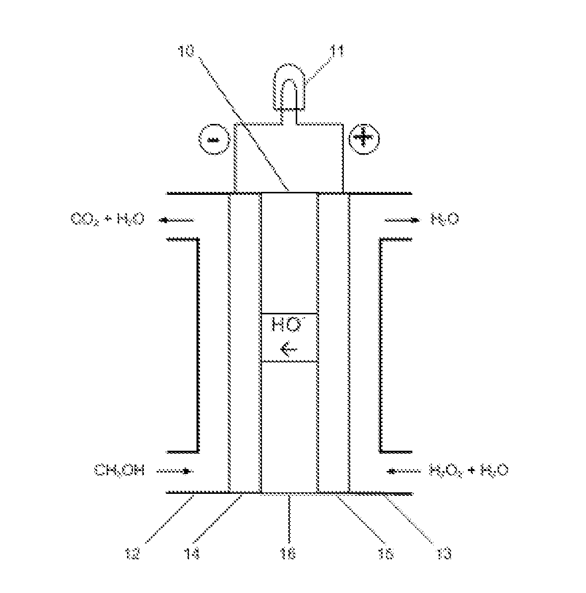
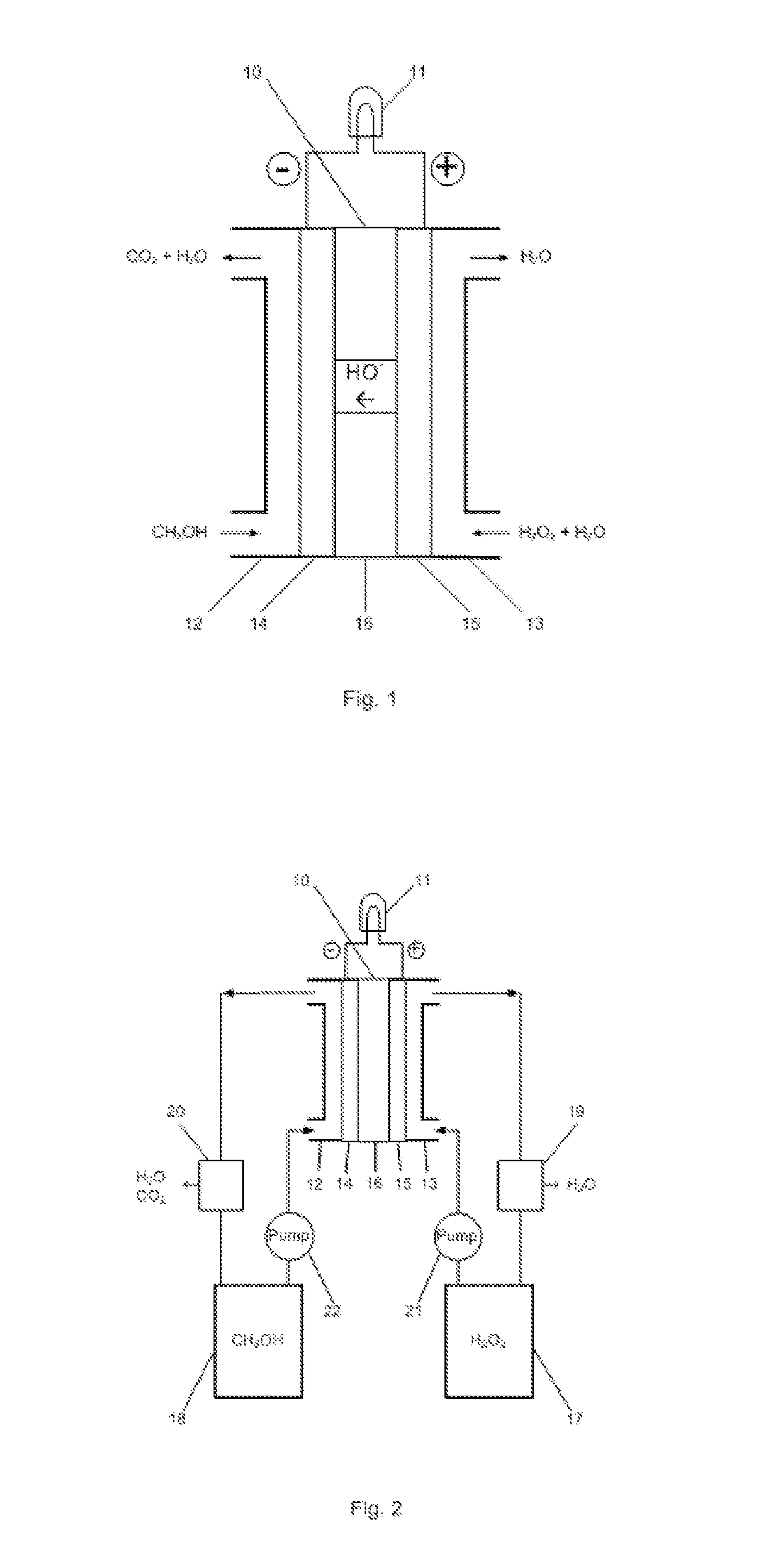
[0011]The embodiments of the present invention are described as following. As shown in FIG. 1, liquid methanol (CH3OH) is fed to an anode compartment 12 in the fuel cell 10. The anode 14 is electrically connected with a load 11 that consumes electrical power. Liquid hydrogen peroxide (H2O2) is fed to a cathode compartment 13 in the fuel cell. The cathode 15 is also connected with the electrical load 11. The anode 14 and cathode 15 are in contact with and separated by a hydroxyl ion electrolyte membrane 16.

[0012]In the fuel cell, hydrogen peroxide is reduced producing hydroxyl ions at the cathode 15:

3H2O2+6e−→6OH−

and methanol is oxidized at the anode 14:

CH3OH-6e−+6OH−→CO2+5H2O

The hydroxyl ions generated at the cathode 15 permeate through the membrane 16 to the anode 14 which react with the hydrogen peroxide and produce carbon dioxide and water. The total reaction is:

CH3OH+3H2O2═CO2+5H2O

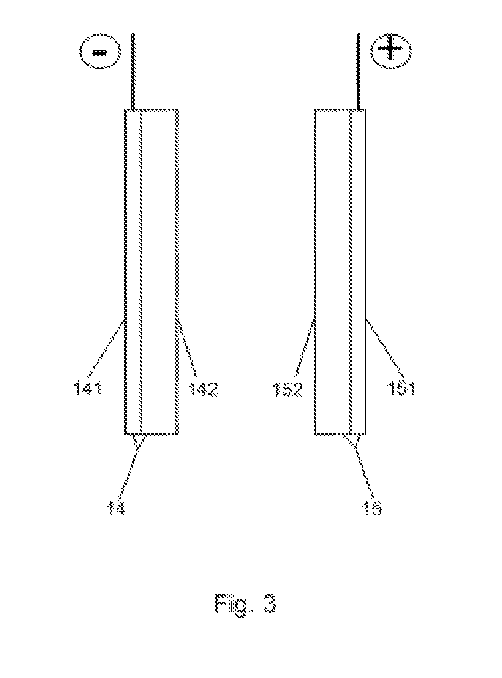
[0013]The anode 14 is formed of porous conductive substrate 141 (FIG. 3) with platinum-ruthenium-pa...


PUM

PropertyMeasurementUnit
temperatureaaaaaaaaaa
electrically conductiveaaaaaaaaaa
ion-conductiveaaaaaaaaaa

Abstract

The fuel cell uses hydrogen peroxide (as oxidant) and methanol (as fuel) to generate electric power and it can operate in a low temperature (20-90° C.). Hydrogen peroxide is used in cathode (coated with catalyst) compartment located at one side of a hydroxyl ion exchange membrane. At the other side of the membrane, methanol is used in anode (coated with catalyst) compartment. A catalytic reduction reaction occurs at cathode to produce hydroxyl ions from hydrogen peroxide, and a catalytic oxidation reaction occurs at anode to produce water and carbon dioxide from methanol. When hydroxyl ions move through electrolyte in the ion exchange membrane from cathode to anode, an electric current is generated accordingly.

Description

CROSS-REFERENCE TO RELATED APPLICATIONS[0001]The present application claims the benefit of U.S. Provisional Patent Application No. 61 / 332,248 filed May 7, 2010. U.S. Provisional Patent Application No. 61 / 332,248 filed May 7, 2010 is hereby incorporated by reference in its entirety.FIELD OF THE INVENTION[0002]The present invention relates to a fuel cell. More specifically, it relates to a direct hydrogen peroxide fuel cell utilizing methanol as fuel, which generates electric current by catalytic reduction of liquid hydrogen peroxide at cathode side coupled with catalytic oxidation of liquid methanol which results in hydroxyl transfer across an ion exchange membrane (with electrolyte).BACKGROUND OF THE INVENTION[0003]The existing problem with hydrogen / hydrogen-peroxide (H / H2O2) is that the energy density is still lower than desired for many applications—particularly as a power supplier for mobile devices. In a H / H2O2 fuel cell, hydrogen peroxide H2O2 is used indirectly to generate oxy...

Claims


Application Information

Patent Timeline
Patent Type & Authority Applications(United States)
IPC IPC(8): H01M8/06H01M8/10
CPCH01M4/8605H01M4/92H01M8/04194Y02E60/523H01M8/1009H01M8/1011H01M8/04291Y02E60/50
Inventor XU, YANG G
Owner XU YANG G
Why Eureka
Try Eureka