
Method and Apparatus For Continuous Production of Carbonaceous Pyrolysis By-Products

a carbonaceous pyrolysis and by-product technology, applied in the field of methods and equipment for the continuous production of carbonaceous pyrolysis by-products, can solve the problems of high engineering and production cost, time-consuming to produce char, and produce a large amount of air pollutants, so as to reduce the risk of explosion, reduce or even eliminate transportation costs, and facilitate movement and deploymen

Inactive Publication Date: 2011-11-17
CARBON RES & DEV CO
View PDF10 Cites 17 Cited by
  • Summary
  • Abstract
  • Description
  • Claims
  • Application Information

AI Technical Summary

Benefits of technology

The present invention provides a method and apparatus for pyrolysis (the process of converting organic materials into gas and char) that can be performed open to the atmosphere, resulting in a safer and more cost-effective process. The invention also allows for the production of carbonized biomass and gaseous pyrolysis by-products with a wide range of physical properties, using a variety of biomass inputs. The invention also has a reduced waste stream, is adaptable to a wide range of feedstock materials, and can be easily moved and deployed in areas where biochar is needed. The invention also provides a biochar material suitable for agricultural and forestry applications, as well as a carbon material that can be used as a substitute for coal in coal burning systems. The invention also allows for the creation of blended products with accelerants, biological materials, nutrients, and other additives.

Problems solved by technology

Both the kiln and retort are simple to construct but time intensive to produce char, and both require loading and unloading between production cycles.
Moreover, without adequate flaring or burn-off of gaseous by-products, these methods can produce a large amount of air pollutants.
A number of other methods, such as microwave pyrolysis and vacuum pyrolysis, exist but are not directly relevant to this application.
When the vessel fills with pyrolysis gas (primarily H2, CO2 and CH4) a significant explosion hazard is created which demands a higher engineering and production cost to ensure the safety of personnel working with the equipment.
These oils can be hazardous to tissues and represent a substantial environmental hazard.
However, as can be seen from the configuration of the system, it is a batch-type operation which requires loading, sealing, heating, unsealing and unloading the retort-a very time consuming process.
Again, the process is not continuous, and requires of loading and unloading of material between cycles.
Further, the char produced by gasification units is generally intended to be used as a fuel and is made at a higher temperature than the temperature required to manufacture char for use as an agricultural amendment, thereby wasting fuel resources.
While gasification systems are able to accept a wide variety of materials, there are few operational systems that can run well for continued periods of time on a broad range of input material.
Feedstock materials must also be dried thoroughly due to gasifiers' limited capabilities to deal with moisture above 7-10%.
Because gasification occurs at temperatures above 800° C. and frequently above 1100° C., gasification equipment construction materials must withstand elevated temperatures, substantially increasing gasification system engineering and construction costs.
If these gases are not properly combusted, they can present a significant air quality and greenhouse gas risk.
Many gasification and pyrolysis units are operated either at such a small scale (camp stoves, two barrel retort) that production of a substantial amount of char for a commercial user is impractical or at such a large scale that feedstocks must be transported over substantial distances to the processing facility.
In such cases, the materials transportation costs quickly become prohibitively expensive, or the CO2 emissions of transportation become larger than the carbon sequestered by the end product.

Method used


Image

  • Method and Apparatus For Continuous Production of Carbonaceous Pyrolysis By-Products
  • Method and Apparatus For Continuous Production of Carbonaceous Pyrolysis By-Products
  • Method and Apparatus For Continuous Production of Carbonaceous Pyrolysis By-Products

Examples


Embodiment Construction

[0034]It should be noted that the present description is by way of instructional examples, and the concepts presented herein are not limited to use or application with any single biomass production and gasification method and / or apparatus. Hence, while the details of the innovation described herein are for the convenience of illustration and explanation with respect to exemplary embodiments, the principles disclosed may be applied to other types and applications of biomass production and gasification methods and apparatus without departing from the scope hereof.

The System:

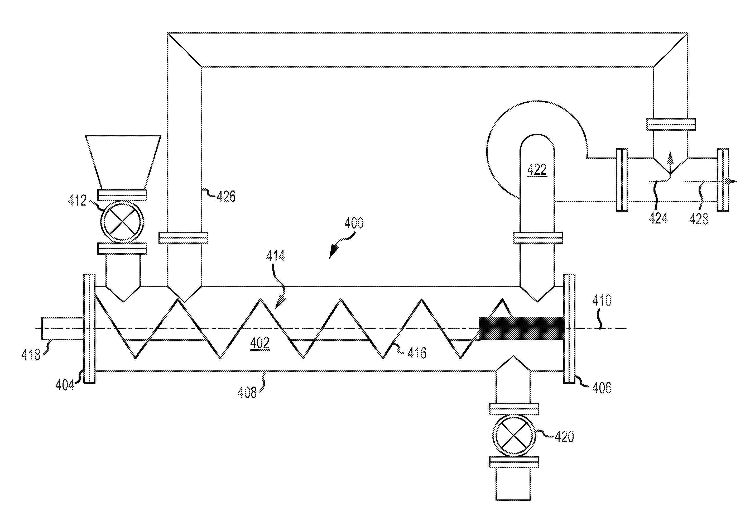
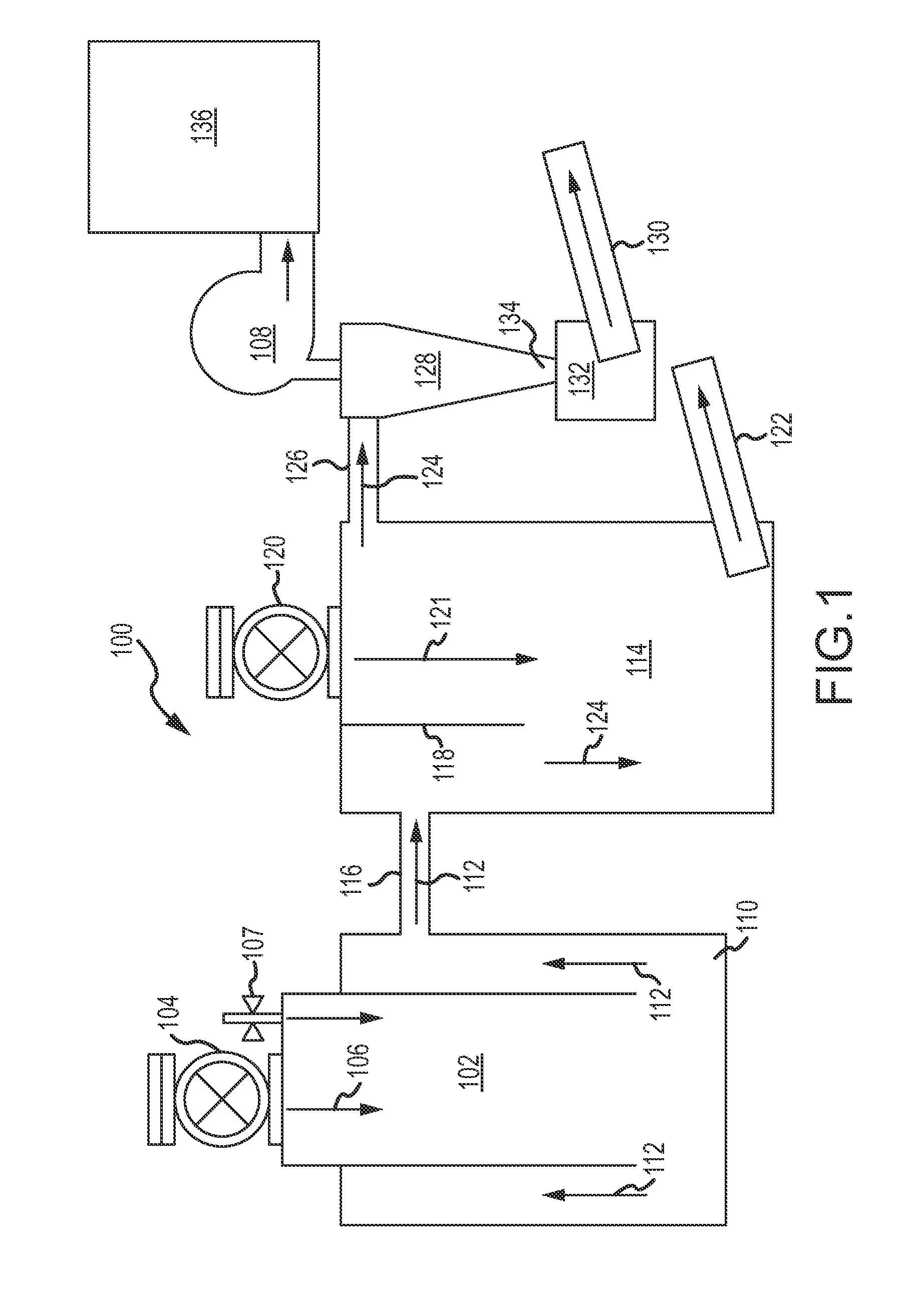
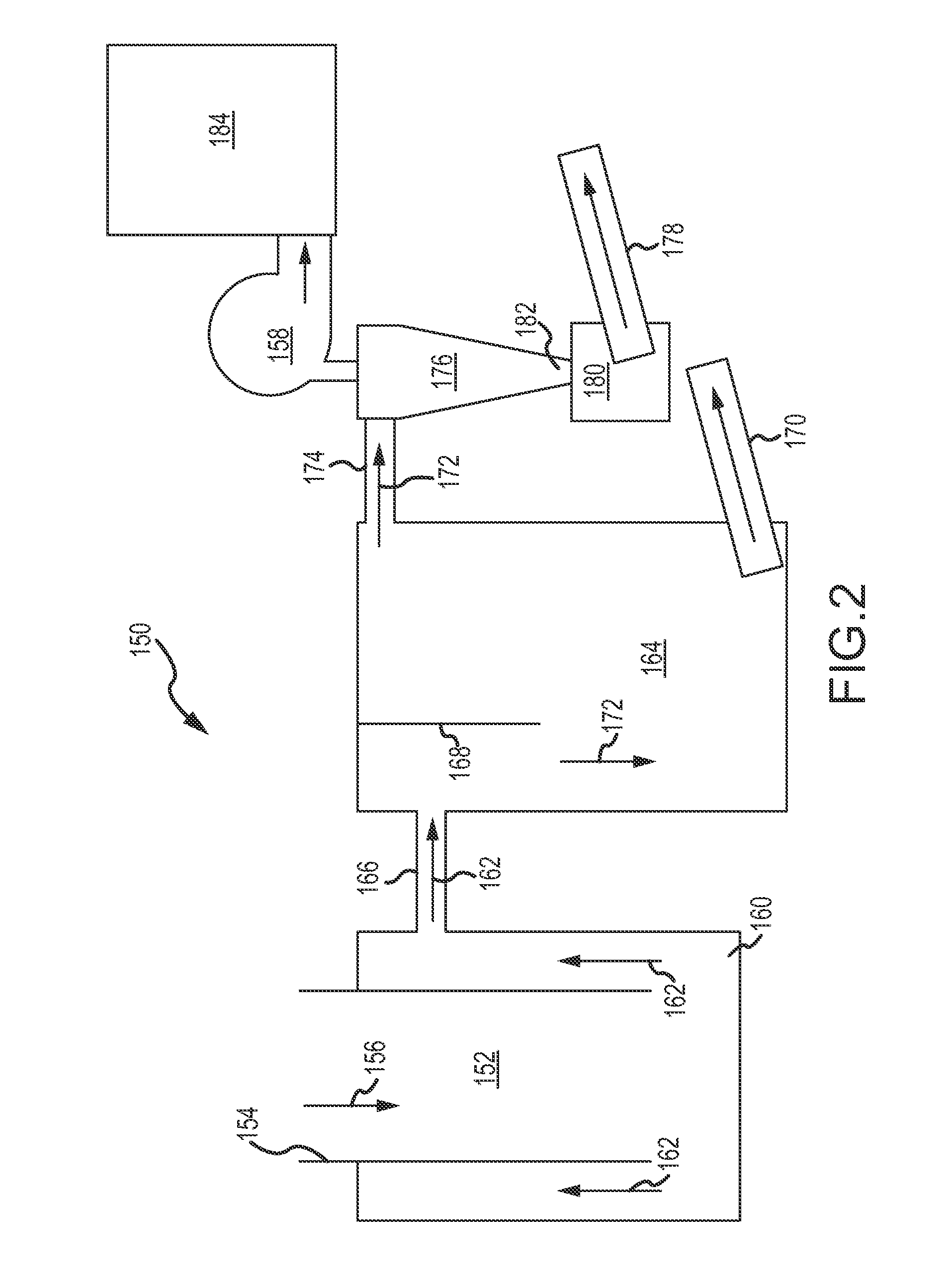
[0035]Referring now to FIG. 1, a system for the continuous production of carbonaceous and gaseous pyrolysis by-products is illustrated generally at 100. For purposes of simplification and the reader's convenience, the terms “biochar”, “char” or “charcoal” will be used herein interchangeably for the term “carbonaceous pyrolysis by-product or by-products”. The system includes a primary pyrolysis / reaction chamber or r...


PUM

PropertyMeasurementUnit
temperaturesaaaaaaaaaa

Abstract

A system and method for the continuous production of carbonaceous pyrolysis by-products are provided which include one or more pyrolysis reaction chambers adapted to receive a wide variety of feedstock materials, including biomass feedstock. System operating parameters including feedstock input rate, atmosphere composition and flow rate, temperature, reaction mixture stirring and agitation rate are selectively independently controllable to produce an end by-product having desired properties for specific applications, and gaseous reaction by-products may be recycled as a fuel for the pyrolysis reaction, thereby enhancing overall system operating efficiency.

Description

CROSS REFERENCE TO RELATED APPLICATIONS[0001]This application claims the benefit or U.S. Provisional Patent Application No. 61 / 331,788 filed May 5, 2010, which is incorporated herein by reference in its entirety as if fully set forth herein.FIELD OF THE INVENTION[0002]The present invention relates generally to a method and apparatus for the continuous production of carbonaceous pyrolysis by-products. More particularly, the present invention relates to a method and apparatus for the production of biochar and gaseous by-products from biomass and other feedstock materials.BACKGROUND OF THE INVENTION[0003]Biochar, more commonly known simply as charcoal, is the solid carbon residue which results from the pyrolysis of various biomass feedstocks such as carbonaceous materials having a cellulosic fibrous structure. Such materials include various types of wood, vegetable biomass, tree bark, paper, paperboard, cardboard, certain waste products, and the like. Pyrolysis is the chemical transfor...

Claims


Application Information

Patent Timeline
Patent Type & Authority Applications(United States)
IPC IPC(8): C10B57/12C10B1/10
CPCC05D9/00C05F11/02C10B49/02C10B49/08Y02E50/14C10B53/02C10B57/02Y02E50/10Y02E50/30C10B49/16Y02P30/20Y02P20/145
Inventor MULQUEEN, DANIEL W.FOURNIER, JAMES L.REED, THOMAS B.
Owner CARBON RES & DEV CO
Learn More