Electric drive apparatus

a motor and drive technology, applied in the direction of windings, magnetic circuit rotating parts, magnetic circuit shapes/forms/construction, etc., can solve the problems of increasing the impedance of electric conductors and the performance of capacitors, and achieves the effect of reducing power source noise, compact size, and attenuating power supply variation

Active Publication Date: 2011-11-24
DENSO CORP
View PDF3 Cites 43 Cited by
  • Summary
  • Abstract
  • Description
  • Claims
  • Application Information

AI Technical Summary

Benefits of technology

[0008]It is therefore an object of the present invention to provide an electric drive apparatus, which is compact in size.
[0009]According to one aspect of the present invention, an electric drive apparatus comprises a motor, a plurality of power modules, a first smoothing capacitor, a choke coil and second smoothing capacitors. The motor has a motor case formed in a cylindrical shape, a stator located radially inside the motor case and coils wound to provide a plurality of phases, a rotor located radially inside the stator and rotatable relative to the stator, and a shaft rotatable together with the rotor. The power modules are located to sandwich a plane including a rotation axis of the shaft therebetween at one axial end side of the shaft. Each of the power modules includes switching elements for switching over

Problems solved by technology

The first bus bars, which connect the capacitors and the power modules, incr

Method used


Image

  • Electric drive apparatus
  • Electric drive apparatus
  • Electric drive apparatus

Examples


first embodiment

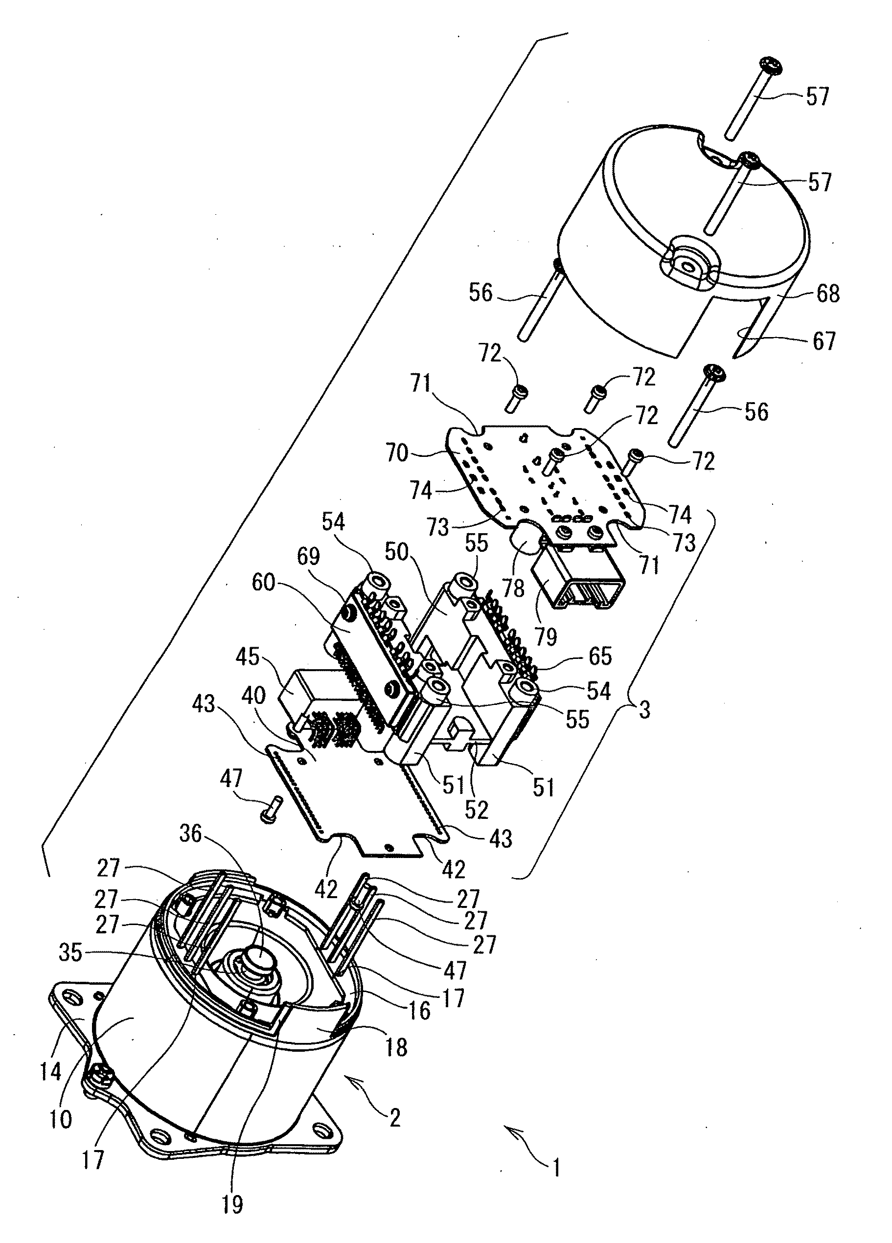
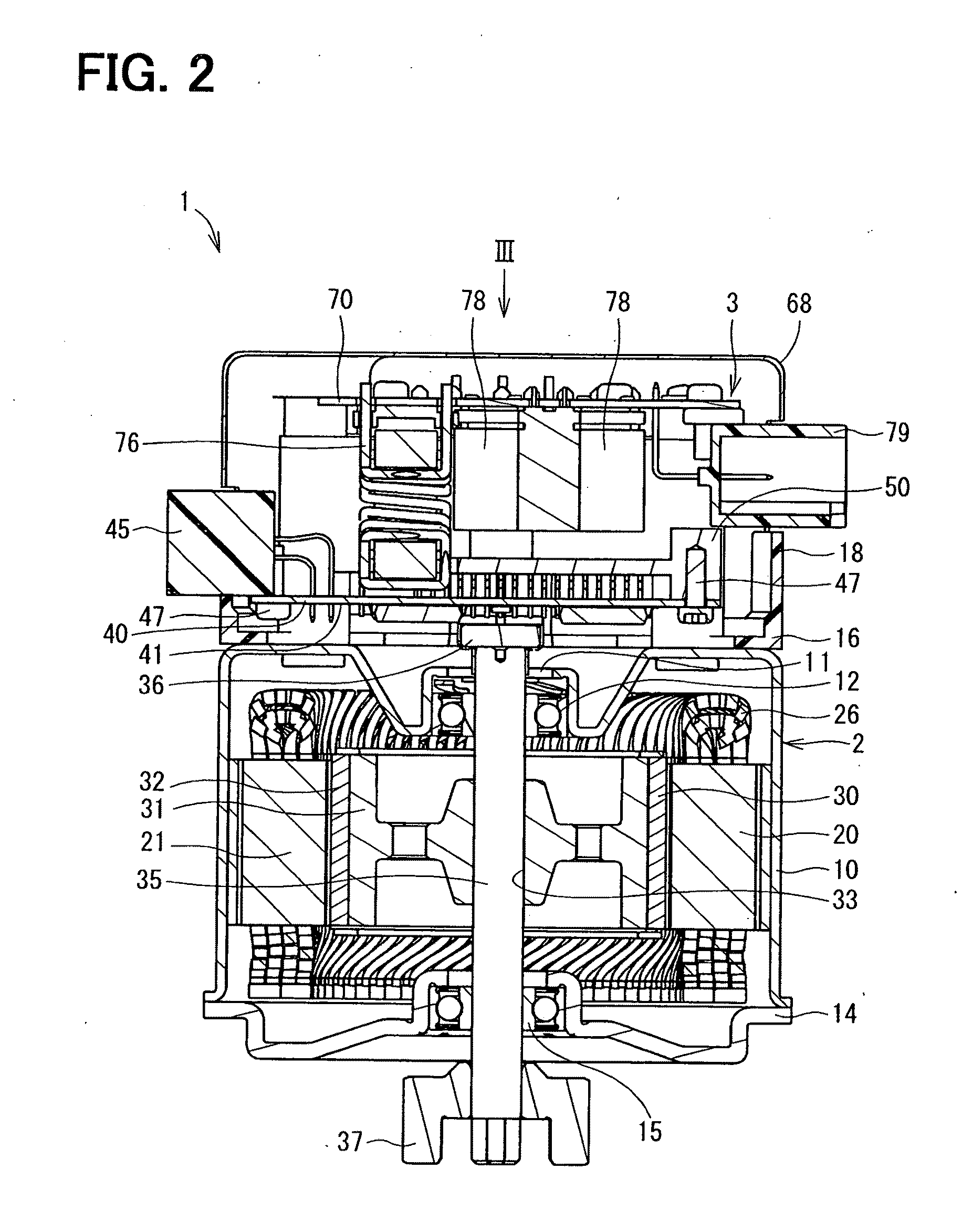
[0051]A drive apparatus according to a first embodiment of the present invention is shown in FIG. 1 to FIG. 17 and referenced by numeral 1. The drive apparatus 1 is applied to an electric power steering system (referred to as EPS) of a vehicle.

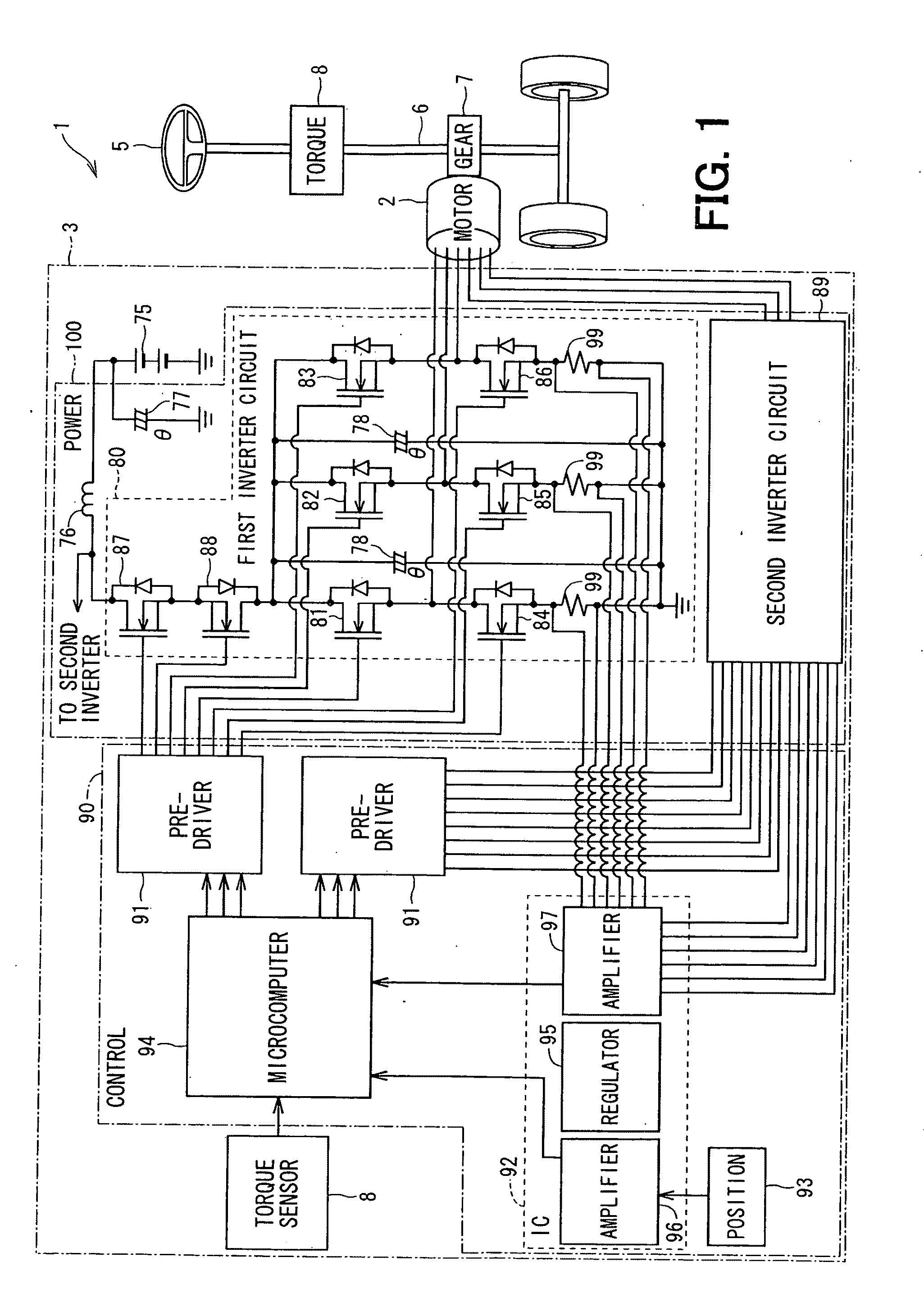
[0052]Electric configuration of the EPS is described first with reference to FIG. 1. The electric configuration described hereunder is applicable to other embodiments. As shown in FIG. 1, the electric drive apparatus 1 is for assisting steering operation of a steering wheel 5 of a vehicle by driving a column shaft 6 to generate rotational torque through a gear 7 attached to the column shaft 6, which is a rotational shaft of the steering wheel 5. Specifically, when the steering wheel 5 is operated by a driver, the electric drive apparatus 1 assists the steering operation of the driver on the steering wheel 5 by detecting steering torque generated in the column shaft 6 and acquiring vehicle speed information from CAN (Controlled Area Network), w...

second embodiment

[0099]An electric drive apparatus according to a second embodiment of the present invention is shown in FIGS. 21 to 29. According to the second embodiment, a heat sink 250 has two heat radiation blocks 251. Two module units 260 and 270 are provided for each of the heat radiation blocks 251. That is, four module units 260 and 270 are mounted on the heat sink 250.

[0100]One module unit 260 is arranged on a top outer wall of the heat radiation block 251, which is at the power circuit substrate 70 side. The other module unit 270 is arranged on a side outer wall of the heat radiation block 251. That is, the semiconductor module unit 260 is arranged to be generally perpendicular to the center of rotation of the shaft 35, and the semiconductor module unit 270 is arranged to be generally in parallel to the center of rotation of the shaft 35.

[0101]The semiconductor module units 260 and 270 has four semiconductor modules 261 to 264 and 271 to 274 as well as metal substrates 265 and 275, respec...

third embodiment

[0113]An electric drive apparatus according a third embodiment of the present invention is shown in FIG. 30 to FIG. 33. This embodiment is a variation of the first embodiment.

[0114]According to the third embodiment, the first smoothing capacitor 77 and the second smoothing capacitors 78 and the choke coil 76 are arranged differently from the first embodiment. These large-sized electronic parts are arranged such that the first smoothing capacitor 77, the choke coil 76 and the second smoothing capacitors 78 are arranged in this order on the power circuit substrate 70 from the power circuit connector 79 side. The second smoothing capacitors 78 are arranged such that the imaginary line Z connecting axes of the second smoothing capacitors 78 forms a square shape when viewed in the axial direction from one axial side of the shaft 35.

[0115]The conductors formed in the power circuit substrate 70 is shown in FIG. 31 to FIG. 33. FIG. 31 shows conductor patterns of a first layer 311 and a four...


PUM


Abstract

Two power modules, in which switching elements for switching over currents supplied to coils of a motor are resin-molded, are provided to face each other sandwiching a plane including a rotation axis of a shaft. A first smoothing capacitor, second smoothing capacitors and a choke coil are located between the power modules. By consolidating large-sized electronic parts between the power modules, a control unit can be reduced in size and impedance of electric conductor connecting the electronic parts and the power modules can be reduced.

Description

CROSS REFERENCE TO RELATED APPLICATION[0001]This application is based on and incorporates herein by reference Japanese patent applications No. 2010-117687 filed on May 21, 2010 and No. 2010-292294 filed on Dec. 28, 2010.FIELD OF THE INVENTION[0002]The present invention relates to a motor and an electric drive apparatus, which has an electronic control unit for controlling drive of the motor.BACKGROUND OF THE INVENTION[0003]In some conventional electric drive apparatuses, which are used for an electric power steering system for assisting steering operation of a driver, an electronic control unit is combined with a motor. The control unit for the electric drive apparatus is required to be compact in size, low in noise and effective to increase output torque of the motor.[0004]According to the following patent documents 1 and 2, three capacitors, which smooth variation in voltage of an input power source, are arranged in as row. In addition, six power modules are located in parallel in...

Claims


Application Information

Patent Timeline
IPC IPC(8): H02K5/22H02K5/18H02K11/02
CPCH02K11/0073H02K11/33
Inventor MIYACHI, SYUHEIYAMASAKI, MASASHIABE, TATSUYA
Owner DENSO CORP
Why Eureka
Try Eureka