Mr imaging with cest contrast enhancement

Inactive Publication Date: 2011-11-24
KONINKLIJKE PHILIPS ELECTRONICS NV
View PDF9 Cites 15 Cited by
  • Summary
  • Abstract
  • Description
  • Claims
  • Application Information

AI Technical Summary

Benefits of technology

[0014]After several cycles of steps a) to c) needed to build up saturation, a virtually full saturation (i.e. a ‘steady-state’ CEST effect) remains in each MR signal acquisition step from the preceding acquisition cycle. An essential feature of the invention is that the duration of the saturation period is (much) shorter (at least by a factor of 5 or 10) than the time required to build up complete saturation when starting from zero saturation. Consequently, the time needed for saturation prior to each MR signal acquisition step is very short according to the invention as compared to conventional CEST imaging approaches. The surprising effect of the invention is that an almost full-sized CEST contrast enhancement effect can be obtained even though the duration of the saturation period is so much shorter than in conventional CEST approaches. This is due to the repetitive re-use of pre-existing saturation generated during previous cycles of steps a) to c).
[0015]As mentioned before, it turns out that after a certain number of repetitions of steps a) to c) of the method of the invention, a steady state of saturation is achieved. In this steady state a complete or nearly complete saturation (plateau) can be made use of for CEST contrast enhancement. It is an important aspect of the invention that the CEST technique may be applied in this steady state of saturation. A significant increase of imaging speed can be obtained because there is no need to wait for a re-build of the saturation prior to each MR signal acquisition step.
[0016]However, it is an import insight of the invention, that MR signal acquisition can start already during the saturation build-up period, i.e. before the steady state is achieved. It typically takes more than a second to approach a steady-state CEST condition. The temporal resolution and speed of the technique of the invention can be significantly increased by using the initial CEST measurements for MR imaging and not (or not only) the steady-state CEST measurements. It is even possible within the scope of the invention to apply the technique in such a manner that the CEST contrast enhancement does not reach a plateau value anymore. Only the initial part of the saturation build-up curve can be measured. With the approach of the invention, a temporal resolution of 10 or more CEST measurements per minute is easily possible, at the expense of an insignificant decrease of the contrast-to-noise ratio. In addition to the increased time resolution and speed, the initial saturation build-up method of the invention has further advantages. For example, the steady-state CEST effect is known to be rather strongly dependent on T1. The initial build-up rate of the CEST contrast enhancement is less dependent on T1 as compared to the steady state CEST effect. For this reason, the initial build-up method of the invention is expected to perform better in tissues with short T1 relaxation times. Moreover, it turns out that the technique of the invention is advantageously less sensitive to direct saturation of bulk water protons, which is one major issue in CEST imaging.
[0017]Especially the combination of the fast CEST MR imaging method of the present invention with existing techniques for rapid MR imaging (like FLASH, EPI and SENSE) constitutes a powerful tool for contrast-enhanced diagnostic MR imaging.
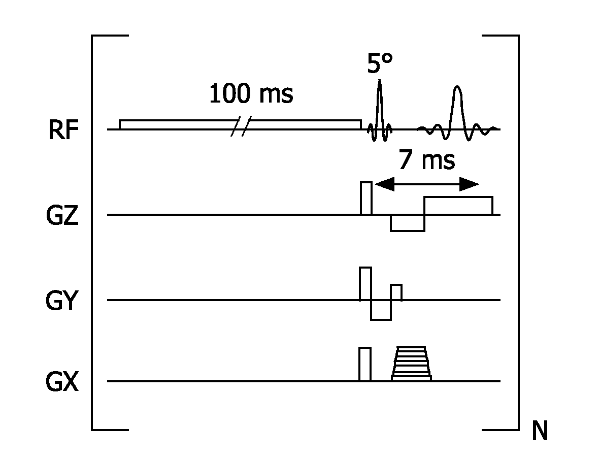
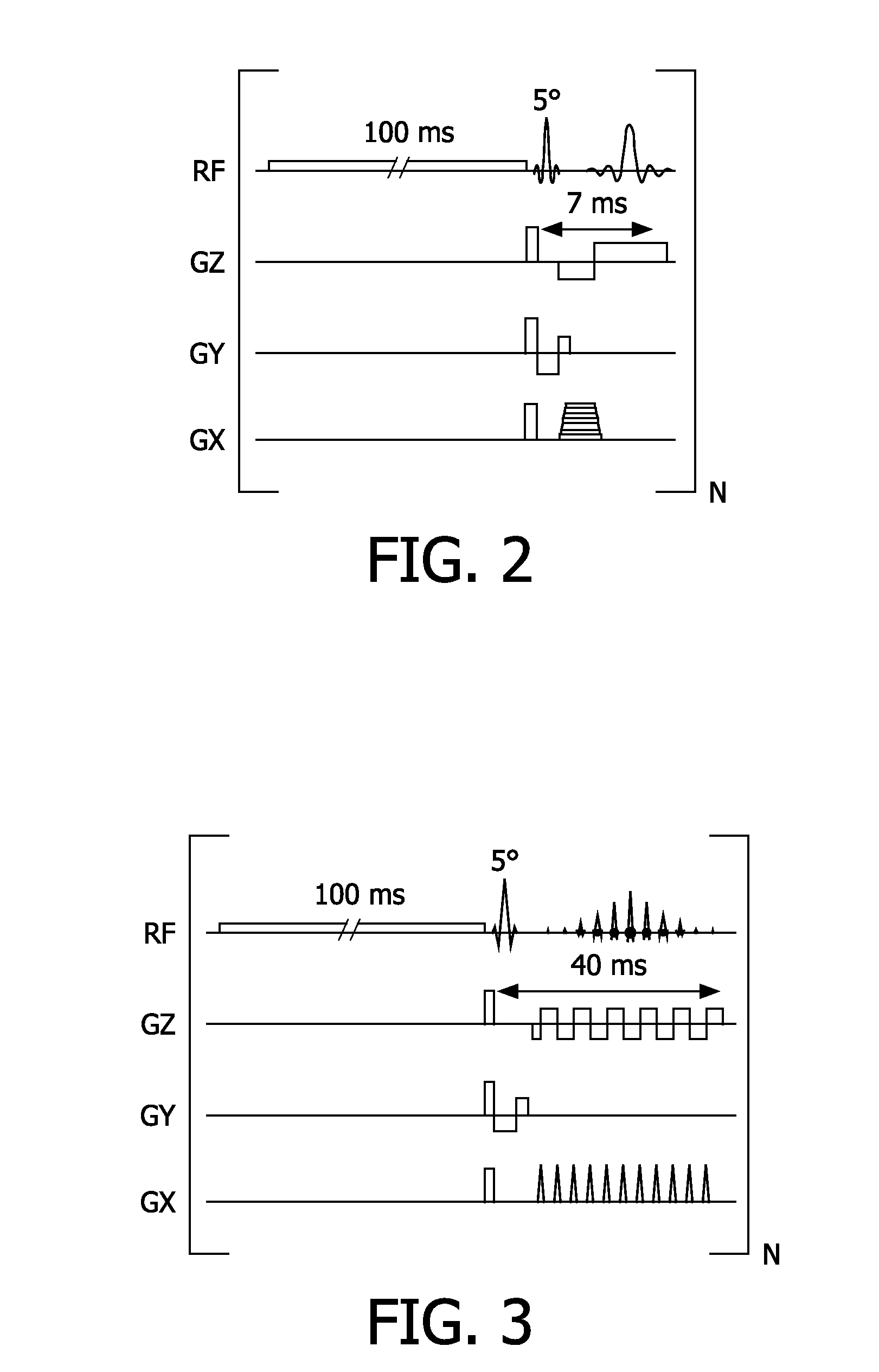
[0018]According to a preferred embodiment of the invention, the duration of the MR imaging sequence in step b) is selected such that saturation remains until irradiation of the subsequent saturation RF pulse in step a). As explained above, if the duration of the saturation and signal acquisition steps are selected properly, saturation remains after each MR signal acquisition step such that the following saturation does not have to start form zero as in the conventional CEST approaches. Preferably, the duration of the MR imaging sequence in step b) is shorter than the duration of the saturation RF pulse in step a). An important aspect of the invention is that the exchangeable protons of the CEST contrast agent are essentially continuously saturated, wherein the generation and acquisition of MR signals for image generation (steps b) and c)) take place during sufficiently short interruptions of the irradiation of the frequency-selective saturation RF pulse. In a preferred embodiment of the method of the invention, the duration of the saturation RF pulse is 1-1000 milliseconds, preferably 2-200 milliseconds, while the duration of the MR imaging sequence is 1-100 milliseconds, preferably 1-50 milliseconds. In this way, a continuous series of CEST-enhanced MR images can be acquired (for example for dynamic or modulated CEST imaging) with a time resolution on the order of only 100 milliseconds or less.
[0019]It is advantageous to use RF pulses with small flip angles)(1-10° for the generation of MR signals in step b), in order to prevent direct saturation of the bulk water MR signal while repeating steps a) to c). However, a small flip angle is not essential for a successful application of the method of the invention. The CEST imaging approach of the invention may also be combined with ‘true FISP’ or ‘balanced FFE’ MR imaging methods. Such gradient-balanced MR imaging techniques effectively help to avoid unwanted direct saturation of the MR signal of water protons of the examined body.

Problems solved by technology

Sometimes the difference in MR signal intensity, i.e. contrast, between different tissues is not sufficient to obtain a satisfactory clinical information and MR contrast agents are then used.
A drawback of all known CEST MR imaging techniques is that the selective saturation prior to the actual acquisition of image data takes a comparably long time.
A further issue in CEST imaging is associated with the lengthy saturation period prior to the actual MR signal acquisition.
The imaging time can easily exceed ten minutes, which has an adverse effect on patient comfort.

Method used


Image

  • Mr imaging with cest contrast enhancement
  • Mr imaging with cest contrast enhancement
  • Mr imaging with cest contrast enhancement

Examples


Embodiment Construction

[0034]With reference to FIG. 1, a main magnet field control 10 controls superconducting or resistive main magnets 12 such that a substantially uniform, temporally constant main magnetic field is created along a z axis through an examination volume 14.

[0035]A magnetic resonance generation and manipulation system applies a series of RF pulses and switched magnetic field gradients to invert or excite nuclear magnetic spins, induce magnetic resonance, refocus magnetic resonance, manipulate magnetic resonance, spatially and otherwise encode the magnetic resonance, saturate spins, and the like to perform MR imaging.

[0036]More specifically, gradient pulse amplifiers 20 apply current pulses to selected ones of pairs of whole-body gradient coils 22 to create magnetic field gradients along x, y and z-axes of the examination volume 14. A digital RF frequency transmitter 24 transmits RF pulses or pulse packets to a hole-body RF coil 26 to transmit RF pulses into the examination volume 14. A typ...


PUM


Abstract

The invention relates to a method of MR imaging of at least a portion of a body of a patient placed in an examination volume of an MR device. The object of the invention is to improve CEST contrast enhanced imaging. The method of the invention comprises the following steps: a) saturation of nuclear magnetization of exchangeable protons of a CEST contrast agent administered to the patient by subjecting the portion of the body to at least one frequency-selective saturation RF pulse matched to the MR frequency of exchangeable protons of the CEST contrast agent, wherein the saturation period, i.e. the duration of the frequency-selective saturation RF pulse, is shorter than the time required for saturation to build up a full CEST contrast enhancement effect when starting from zero saturation; b) generating at least one MR signal of water protons of the body by subjecting the portion of the body to an MR imaging sequence comprising at least one RF pulse and switched magnetic field gradients; c) acquiring sampling the at least one MR signal from the body; d) repeating steps a) to c) a number of times under variation of parameters of the MR imaging sequence, wherein MR signals are acquired and sampled during a saturation build-up period, i.e. before a steady state of the CEST effect is achieved; e) reconstructing a proton-density weighted, CEST contrast-enhanced MR image from the acquired and sampled MR signals.

Description

BACKGROUND OF THE INVENTION[0001]The invention relates to the field of magnetic resonance (MR) imaging. It concerns a method of MR imaging of at least a portion of a body of a patient placed in an examination volume of an MR device. The invention also relates to an MR device and to a computer program to be run on an MR device.[0002]Image-forming MR methods which utilize the interaction between magnetic fields and nuclear spins in order to form two-dimensional or three-dimensional images are widely used nowadays, notably in the field of medical diagnostics, because for the imaging of soft tissue they are superior to other imaging methods in many respects, do not require ionizing radiation and are usually not invasive.[0003]According to the MR method in general, the body of the patient to be examined is arranged in a strong, uniform magnetic field whose direction at the same time defines an axis (normally the z axis) of the co-ordinate system on which the measurement is based. The mag...

Claims


Application Information

Patent Timeline
IPC IPC(8): A61B5/055
CPCG01R33/5616G01R33/5601
Inventor PIKKEMAAT, JEROEN ALPHONSLANGEREIS, SANDERGRUELL, HOLGERBURDINSKI, DIRKLAMERICHS, RUDOLF MATHIAS JOHANNES NICOLAASKEUPP, JOCHEN
Owner KONINKLIJKE PHILIPS ELECTRONICS NV
Why Eureka
Try Eureka