Low voltage low power CMOS temperature sensor circuit

a temperature sensor and low-power technology, applied in the field of low-voltage low-power cmos temperature sensor circuits, can solve the problems of increasing circuit complexity and chip area, not suitable for passive rfid tag applications, and reducing power consumption and snr (signal-to-noise ratio) improvement, and reducing power and area overhead

Active Publication Date: 2011-12-01
THE HONG KONG UNIV OF SCI & TECH
View PDF1 Cites 44 Cited by
  • Summary
  • Abstract
  • Description
  • Claims
  • Application Information

AI Technical Summary

Benefits of technology

[0012]The sensor core is connected to PTAT and CTAT delay generators and a low voltage time-domain differential readout circuit for reduction of power consumption and SNR (signal-to-noise ratio) improvement. The readout circuit performs an XOR function on the outputs of the PTAT and CTAT delay generators to obt...

Problems solved by technology

This is because passive RFID tags harvest power through rectification of the incoming RF signal, and the total energy available is limited.
These sensors generally achieve good accuracy but are associated with penalties of increased circuit complexity and chip area.
The corresponding power consumption is usually in the μW range and is therefore not suitable for passive RFID tag applications.
These time domain sensors, though having increased inaccuracy, us...

Method used


Image

  • Low voltage low power CMOS temperature sensor circuit
  • Low voltage low power CMOS temperature sensor circuit
  • Low voltage low power CMOS temperature sensor circuit

Examples


Embodiment Construction

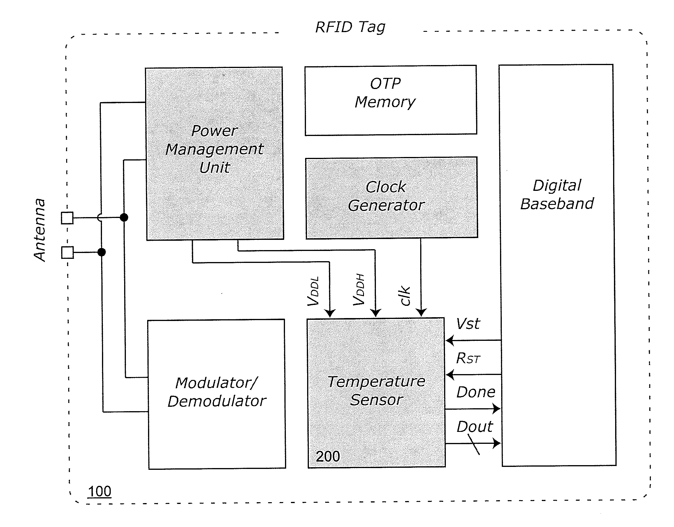
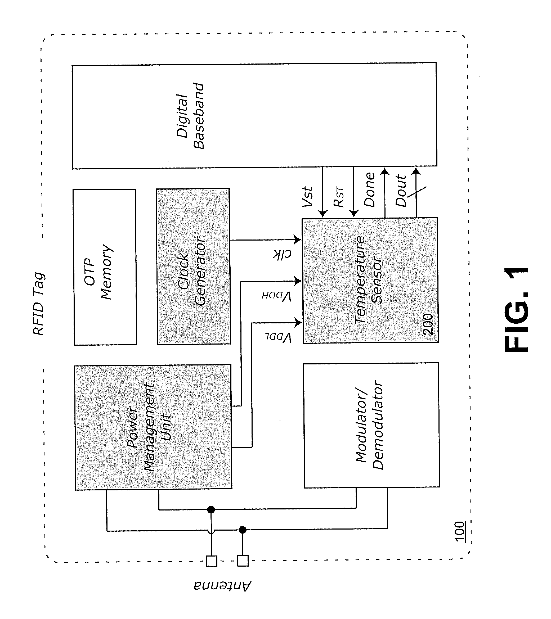
[0029]With reference to FIG. 1, a block diagram is depicted showing components of an RFID tag 100 that may be used with embodiments of the present invention. The RFID tag 100 generally includes an antenna, a power management unit (PMU), a modulator / demodulator, an OTP (one-time programmable) memory, a clock generator, a temperature sensor, and a digital baseband. The PMU rectifies incoming RF signals to generate supply voltages for the other building blocks, including the temperature sensor, and provides analog biasing and a power-on-reset (POR) signal for analog and digital modules, respectively. The clock generator produces the system clock for synchronization as well as sensor signal quantization. The modulator changes the tag's input impedance to control whether the incoming power from the reader is absorbed by the tag or reflected to the reader for tag data transmission, while the demodulator removes the carrier frequency to recover the data symbols. The digital baseband is uti...


PUM


Abstract

The present invention provides an ultra-low power embedded CMOS temperature sensor based on serially connected subthreshold MOS operation particularly well suited for passive RFID food monitoring applications. Employing serially connected subthreshold MOS as sensing element enables reduced minimum supply voltage for further power reduction, which is very important in passive RFID applications. The temperature sensor may be part of a passive RFID tag and incorporates a temperature sensor core, proportional-to-absolute-temperature (PTAT) and complimentary-to-absolute-temperature (CTAT) delay generators, and a time-to-digital differential readout circuit. In one embodiment, the sensor is embedded inside a passive UHF RFID tag fabricated with a conventional 0.18 μm 1P6M CMOS process. With the sensor core working under 0.5 V and digital interfacing under 1 V, the sensor dissipates a measured total power of 119 nW at 33 samples/s and achieves an inaccuracy of +1/−0.8° C. from −10° C. to 30° C. after calibration.

Description

CROSS-REFERENCE TO RELATED APPLICATIONS[0001]This patent application claims the benefit of U.S. Provisional Patent Application No. 61 / 344,123, filed May 27, 2010, which is incorporated by reference in its entirety.BACKGROUND OF THE INVENTION[0002]Unlike traditional temperature sensors that utilize offchip components, on-chip CMOS (complementary metal-oxide-semiconductor) temperature sensors are well-known for their benefits of low production cost and ability to interface easily with other electronic circuits. On-chip temperature sensors with small area and low power consumption are normally employed in thermal management applications in order to monitor system reliability and performance as a result of temperature variation.[0003]One popular use of embedded temperature sensors in very-large-scale integration (VLSI) implementations is to monitor excess on-chip heat dissipation resulting from higher and higher levels of integration. On the other hand, the emergence of radio frequency ...

Claims


Application Information

Patent Timeline
IPC IPC(8): G06K7/01G01K7/01
CPCG01K7/01G06K19/0723G06K19/0717
Inventor LAW, MAN KAYBERMAK, AMINELUONG, HOWARD CAM
Owner THE HONG KONG UNIV OF SCI & TECH
Why Eureka
Try Eureka