Process for Beamforming Data to be Transmitted by a Base Station in a MU-MIMO System and Apparatus for Performing the Same

a technology of beamforming data and communication system, which is applied in the field of digital wireless communication, can solve the problems of dpc, which is acknowledged to be fairly complex for a practical implementation in a commercial product, and the performance obtained with this scheme is highly suboptimal, and limits the selection of the best users that the enodeb can sel

Inactive Publication Date: 2011-12-08
ST ERICSSON FRANCE +1
View PDF3 Cites 110 Cited by
  • Summary
  • Abstract
  • Description
  • Claims
  • Application Information

AI Technical Summary

Benefits of technology

[0011]It is an object of the present invention to provide an optimal, complete and generic construction of a unitary beamformer under the constant modulus constraint.
[0012]It is a further object of the present invention to provide an optimal structure for a constant modulus unitary beamforming (current assumption in LTE standard) which could be used in LTE standard Rel 9 / LTE-Advanced standard.
[0013]It is a further object of the present invention to provide an efficient / optimal precoding of the signal transmitted by a eNodeB (base station in LTE) to several UEs when the former employs multiple antennae.
[0014]It is still another object of the present invention to improve the performance of the multi-user MIMO (Multiple Input Multiple Output) strategy currently standardized for Rel 8 LTE standard.

Problems solved by technology

The capacity is achieved by using a technique called Dirty Paper Coding, DPC, which is acknowledged to be fairly complex for a practical implementation in a commercial product.
The performance obtained with this scheme is highly suboptimal, because the set of available precoding matrices is too small and it can not be well adapted to the short term average characteristic of the MIMO broadcast channel.
The eNodeB will schedule only a set of UEs which have fed back the same precoding index, which limits the choice of the best users that the eNodeB can select.
The performance obtained with this scheme is highly suboptimal, because the set of available precoding matrices is too small and it can not be well adapted to the short term average characteristic of the MIMO broadcast channel.
This method is in conclusion not suitable because it does not fully exploit the benefit of a multi-user environment / diversity and does not exploit all the possible degrees of freedom available in the system.

Method used


Image

  • Process for Beamforming Data to be Transmitted by a Base Station in a MU-MIMO System and Apparatus for Performing the Same
  • Process for Beamforming Data to be Transmitted by a Base Station in a MU-MIMO System and Apparatus for Performing the Same
  • Process for Beamforming Data to be Transmitted by a Base Station in a MU-MIMO System and Apparatus for Performing the Same

Examples


Embodiment Construction

A. Preliminary Notation and System Model

[0059]In the following boldface lower-case and uppercase characters denote vectors and matrices, respectively. The operators (·)T, (·)H and tr(·) denote transpose, conjugate transpose and trace of a matrix, respectively. The expectation is E[−] and diag(x) is a diagonal matrix with vector x on the main diagonal. The N×N identity matrix is IN.

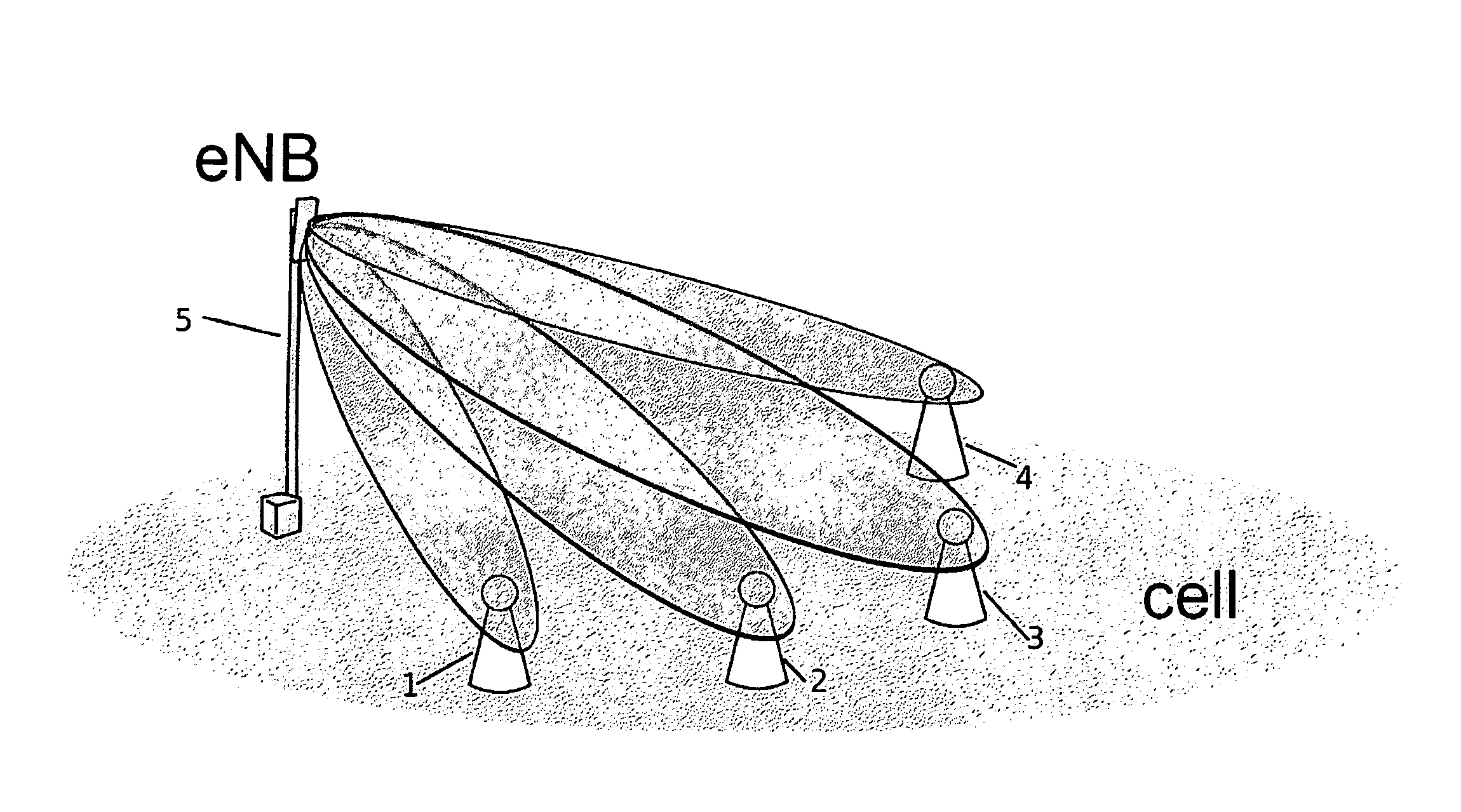
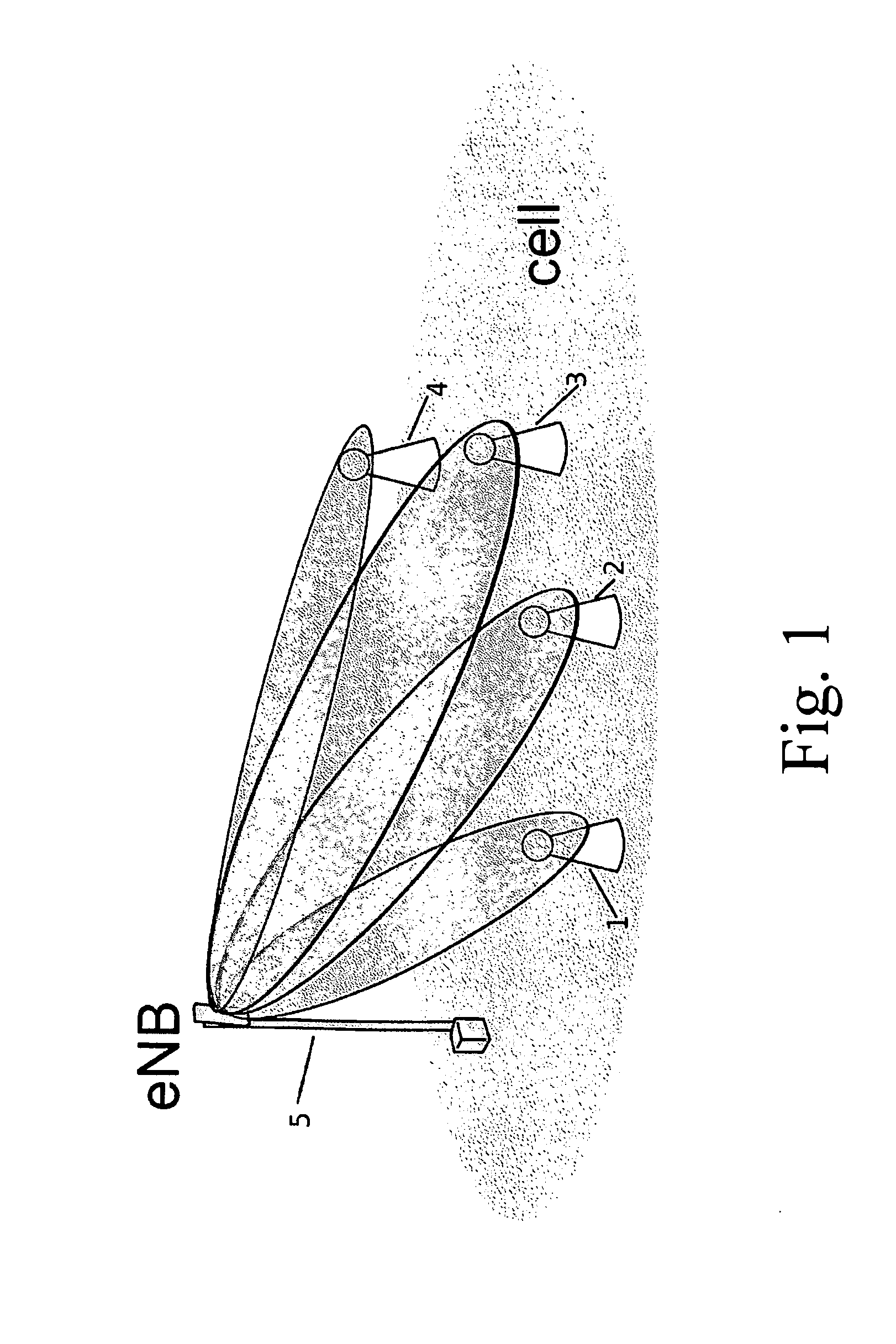
[0060]There is assumed a scenario where one transmitter with M antennas communicates to K single-antenna receivers. Furthermore it is supposed that there are always K=M users selected for transmission. A beamforming vector vk is assigned to each of the K users, where we define the beamforming matrix as

Vcu=[v1 . . . vk]εM×K

[0061]The transmit signal is formed as:

x=∑k=1Mpkvksk

where pk and sk are the power and the information symbol of user k, respectively.

[0062]The instantaneous sum-rate of the users is given by the following formulas

=∑k=1Mlog2(1+γk)withγk=hk2ρk2hk2(1-ρk2)+σn2pk

with ρk2=| hkHvk|2,

h_k=hkhk.

He...


PUM


Abstract

A process for beamforming data to be transmitted in a MU-MIMO communication system comprising a base station and a selected set of User Equipments (UE) communicating with said base station; said data being precoded by said base station in accordance with a beamforming matrix complying with a precoding matrix under the form of: (formula 1) Where—M is the number of transmit antennas—D is a diagonal unitary matrix of the form D=diag (formula 2)—P is a permutation matrix interchanging only the last M−1 rows. —A is a general Hadamard matrix. and that the signaling information transmitted by the base station to the UE comprises at least a first and a second index which are representative of D, P and A.

Description

TECHNICAL FIELD[0001]The present invention relates to digital wireless communications and more particularly to a process for beamforming data to be transmitted by a base station in a MU-MIMO communication system, and apparatus for performing the same.BACKGROUND ART[0002]Multiple-Input Multiple-Output (MIMO) systems have the potential to significantly increase the peak throughput. Although peak data rates are often a compelling marketing argument for emerging wireless standards, most of the network operators are interested in increasing their cell throughput or to distribute rates more uniformly within a cell. Instead of focusing on a single user (SU-MIMO) the base-station employs its antennas to communicate to multiple non-cooperative users (MU-MIMO) on the same time-frequency resource. In order to reduce the interference caused by the imperfect spatial separation of the users the base station can encode the signal prior to the transmission. This precoding (or beamforming) scheme an...

Claims


Application Information

Patent Timeline
Patent Type & Authority Applications(United States)
IPC IPC(8): H04J11/00
CPCH04B7/0417H04B7/0452H04B7/0465H04B7/0619H04B7/0617
Inventor SESIA, STEFANIASLOCK, DIRKWAGNER, SEBASTIAN
Owner ST ERICSSON FRANCE
Why Eureka
Try Eureka