Supercharge Your Innovation With Domain-Expert AI Agents!

X-ray waveguide

a waveguide and waveguide technology, applied in the field of x-ray waveguides, can solve the problems of narrow design range, difficult x-ray guide, limited material selectivity, etc., and achieve the effect of efficiently guiding an x-ray and high selectivity of its components

Inactive Publication Date: 2011-12-08
CANON KK
View PDF1 Cites 7 Cited by
  • Summary
  • Abstract
  • Description
  • Claims
  • Application Information

AI Technical Summary

Benefits of technology

The present invention provides an X-ray waveguide with high selectivity and efficient guiding of X-rays. It includes a core for guiding X-rays in a wavelength band where the refractive index of a material is 1 or less, and a cladding for confining the X-rays in the core. The cladding has a periodic structure with multiple materials having different refractive indices arranged in two-dimensional directions perpendicular to the guiding direction of X-rays. The periodic structure has a period of 100 nm or less. This design allows for efficient guiding of X-rays and ensures high selectivity of the waveguide components.

Problems solved by technology

Therefore, with the configuration, it is difficult to guide the X-ray by confining the X-ray in the core.
Accordingly, there arises such a problem that the selectivity of materials is limited and the range of designs narrows.
In addition, when only the total reflection is used, individual structure errors such as instabilities at the time of production present at the interface between the core and the cladding, and further, in the core and the cladding, the unavoidable discontinuity of the interface, and a crack cause serious reductions in propagation characteristics such as a reduction in transmittance and the deterioration of a waveguide mode.
Further, when an X-ray is guided by using only the total reflection, the waveguide mode itself also depends only on the material and a structure determined by the material, and hence the mode is hard to control freely.
However, the one-dimensional periodic structure exerts its effect almost only in the direction perpendicular to a substrate surface, and cannot exert the effect in a direction parallel to the substrate surface.
Accordingly, there arises such a problem that it is extremely difficult to control a mode parallel to the surface or waveguiding direction.

Method used


Image

  • X-ray waveguide
  • X-ray waveguide
  • X-ray waveguide

Examples


example 1

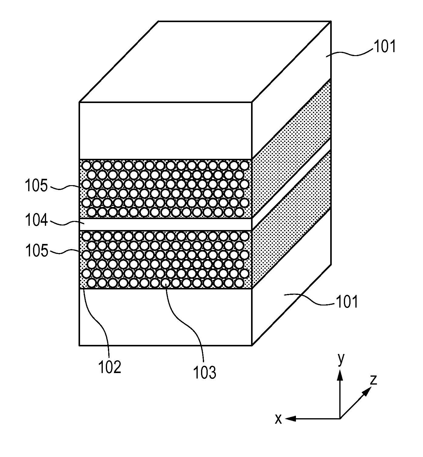
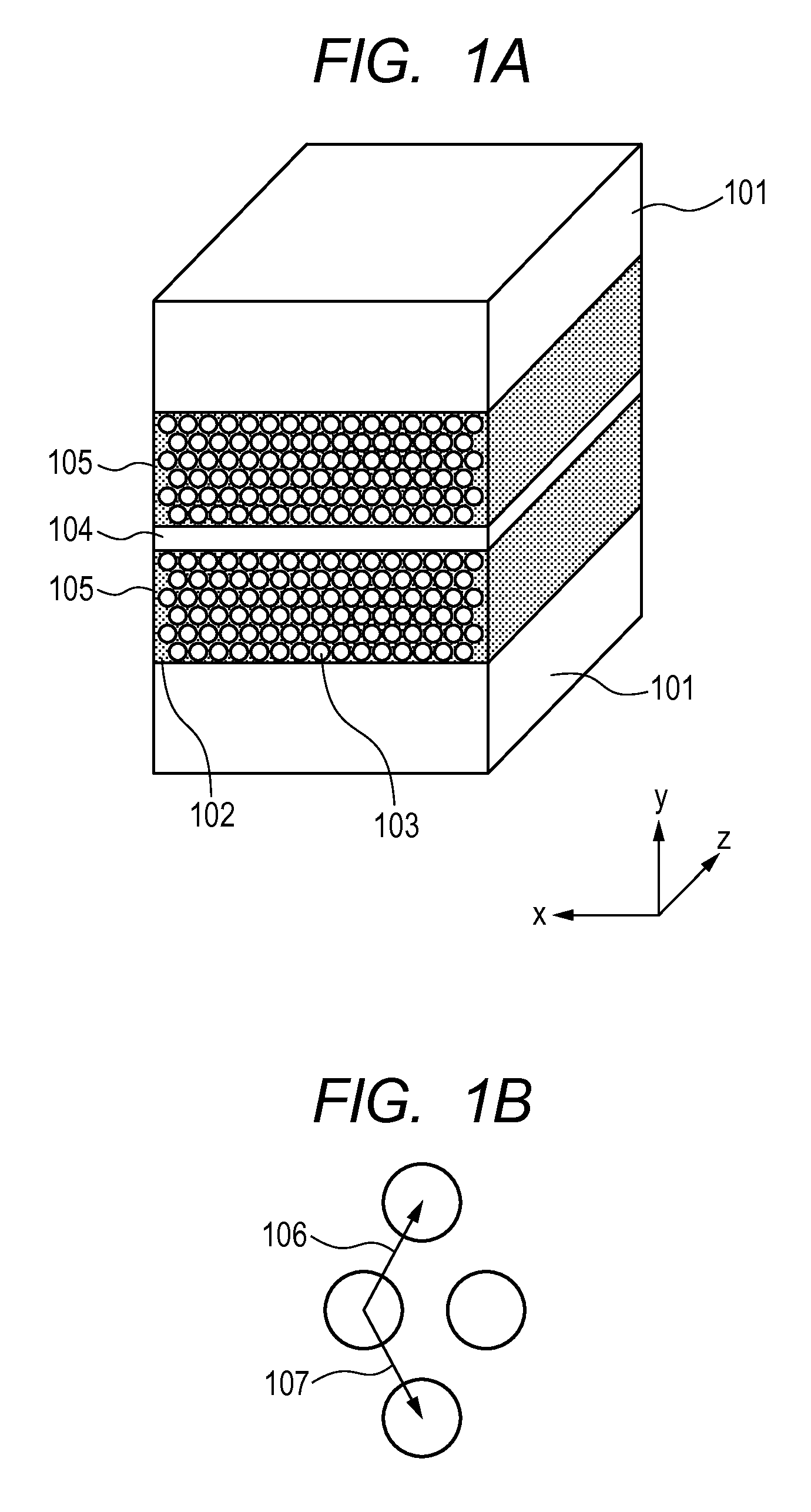
[0039]In the present invention, the waveguiding direction of an X-ray to be guided is parallel to a z-axis in each figure in each of all examples. In other words, a wave vector equivalent to the propagation constant of a waveguide mode is identical in direction to the z-axis. Example 1 of the present invention is described with reference to FIGS. 1A and 1B. The X-ray waveguide illustrated in FIGS. 1A and 1B is obtained by sandwiching the core with claddings 105, which are each a mesoporous silica film formed on a Si substrate 101 and having a thickness of about 300 nm, so that a core 104 formed of polymethyl methacrylate (PMMA) may be interposed between the claddings.

[0040]Each of the claddings 105 as the mesoporous silica films is such that pores 103 of a surfactant as an organic material, the pores elongating in a z direction in FIGS. 1A and 1B and each having a radius of about 2 nm, form a triangular lattice periodic structure in SiO2 102 in an x-y plane. The period is about 5 nm...

example 2

[0042]FIG. 6 is a view illustrating Example 2 of the present invention. An X-ray waveguide of FIG. 6 is of the following shape. A cladding 703 is provided on an Si substrate 701, a core 702 is provided on the cladding 703, and further, a cladding 704 is provided on the core 702. In addition, the core 702 is interposed between the two claddings 703 and 704. The core is, for example, air. The cladding 703 is of the so-called artificial opal structure where polystyrene spheres each having a diameter of about 50 nm are arranged into a hexagonal close-packed structure in a self-organizing fashion on the substrate, and is of a three-dimensional periodic structure. The cladding 704 is formed of Ni. The Ni film of the cladding 704 has a real part of the refractive index of about 0.9999877410 for an X-ray having a photon energy of about 12 keV. In addition, the cladding 703 is formed of the styrene spheres each having a real part of the refractive index of about 0.9999965852 and polymethyl m...

example 3

[0044]FIG. 7 is a view illustrating Example 3 of the present invention. In this example, the core of the X-ray waveguide described in Example 1 is of a structure patterned in a two-dimensional plane, and the configuration except a core 804 and a spacer 805 is the same as that of Example 1.

[0045]In this example, in a forming process for the core, Ti 805 is formed on a mesoporous silica 806 as one cladding by sputtering so as to have a thickness of 50 nm, and then the core 804 having a width of about 200 nm and formed of air is formed by electron beam lithography and etching. Further, the mesoporous silica 806 produced on an Si substrate 801 is stuck onto the core. The mesoporous silica 806 is such that pores 803 of a surfactant as an organic material, the pores elongating in a z direction in FIG. 7 and each having a radius of about 2 nm, form a triangular lattice-like periodic structure in SiO2 802 in an x-y plane. As the core is patterned in the two-dimensional plane, an X-ray in th...


PUM


Abstract

An X-ray waveguide according to the present invention includes: a core for guiding an X-ray in such a wavelength band that a real part of the refractive index of a material is 1 or less; and a cladding for confining the X-ray in the core, wherein: the cladding has a periodic structure in which multiple materials having different real parts of the refractive index are periodically arranged in two-dimensional directions perpendicular to the guiding direction of X-ray; and the periodic structure has a period of 100 nm or less.

Description

BACKGROUND OF THE INVENTION[0001]1. Field of the Invention[0002]The present invention relates to an X-ray waveguide, and more specifically, to an X-ray waveguide to be used in an X-ray optical system for an X-ray analysis technology, an X-ray imaging technology, an X-ray exposure technology, or the like.[0003]2. Description of the Related Art[0004]When an electromagnetic wave having a short wavelength of several ten nanometers or less is dealt with, a difference in refractive index for any such electromagnetic wave between different materials is extremely small, specifically, 10−5 or less. Hence, the critical angle for total reflection also becomes extremely smaller. In view of the foregoing, a large-scale spatial optical system has been used for controlling such electromagnetic wave including an X-ray, and has still been in the mainstream now. As main parts for forming the spatial optical system, there is given a multilayer mirror obtained by alternately laminating materials having...

Claims


Application Information

Patent Timeline
Patent Type & Authority Applications(United States)
IPC IPC(8): G21K1/00
CPCG21K2201/067G21K1/067
Inventor OKAMOTO, KOHEIKOMOTO, ATSUSHIKUBO, WATARUMIYATA, HIROKATSUNOMA, TAKASHI
Owner CANON KK
Features
  • R&D
  • Intellectual Property
  • Life Sciences
  • Materials
  • Tech Scout
  • Unparalleled Data Quality
  • Higher Quality Content
  • 60% Fewer Hallucinations
Learn More