
Scatterometry Method and Measurement System for Lithography

Active Publication Date: 2011-12-15
ASML NETHERLANDS BV
View PDF1 Cites 11 Cited by
  • Summary
  • Abstract
  • Description
  • Claims
  • Application Information

AI Technical Summary

Benefits of technology

[0008]It is desirable to improve the accuracy and robustness with which high-resolution structures can be measured with scatterometry-based metrology, and hereby extend the application scope of scatterometry-based metrology to high resolutions that were not within reach for this method of metrology.

Problems solved by technology

Moreover, information about structures that is beyond the diffraction limit is intrinsically more difficult to be retrieved, and parameters of the diffracting pattern may be highly correlated such that unambiguous and robust reconstruction may be hampered, just because of the fact that the information about the diffracting structure that is present in the back focal plane intensities is just too sparse.

Method used


Image

  • Scatterometry Method and Measurement System for Lithography
  • Scatterometry Method and Measurement System for Lithography
  • Scatterometry Method and Measurement System for Lithography

Examples


example

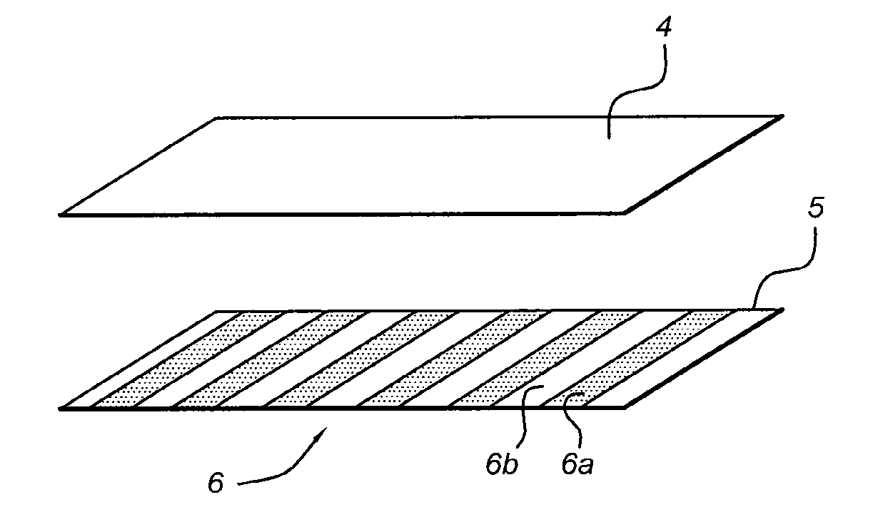
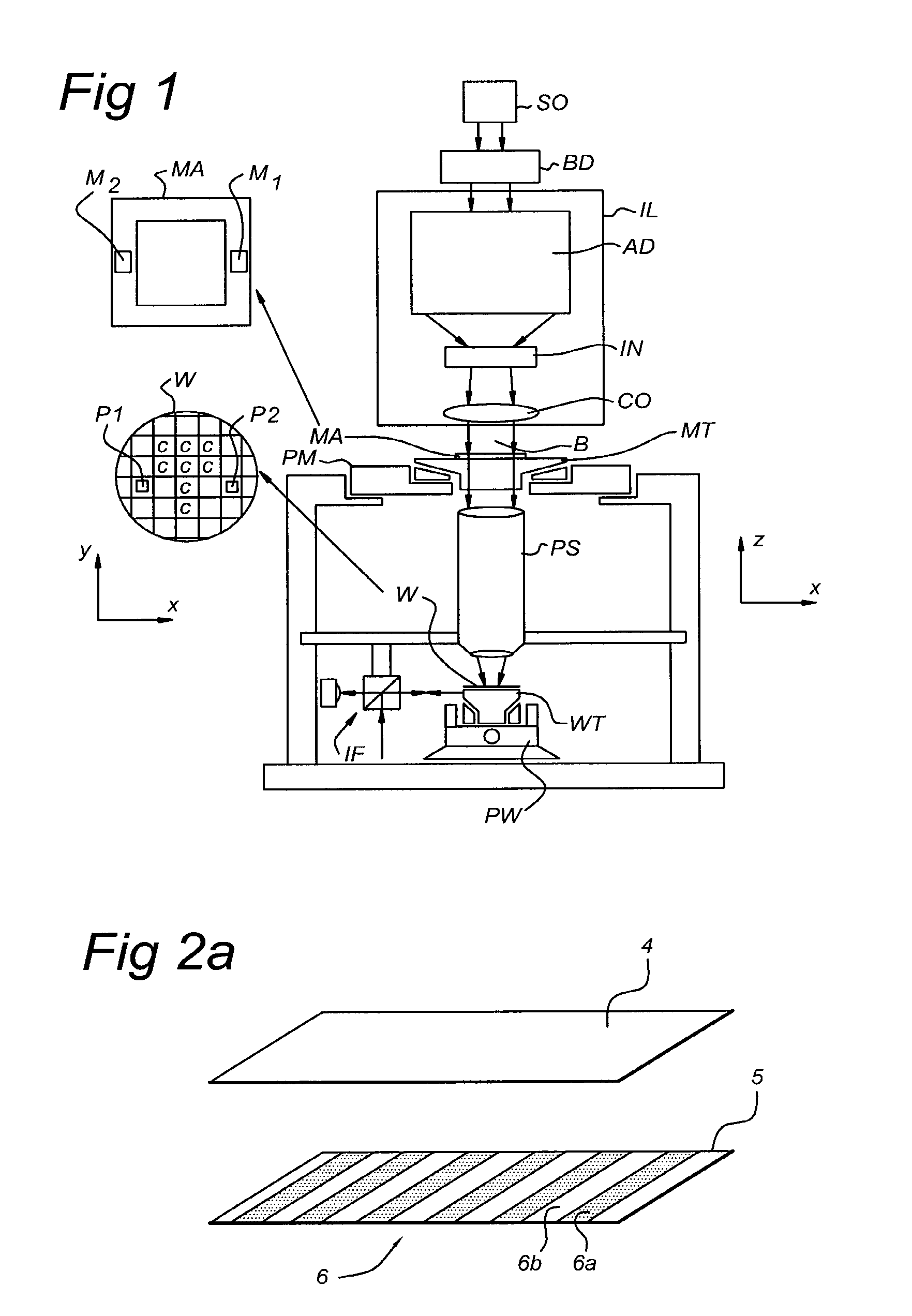
[0062]In the FIG. 4 embodiment, an example is shown of a two layer sandwich structure on a substrate W. The bottom layer 5 comprises a bottom part 5a having a low frequency grating 6 with Si lines 6a. The bottom layer 5 further comprises a bottom anti-reflective coating 5b, forming the spaces 6b of the low frequency grating 6. The top layer 4 comprises a resist layer 4a, in which lines 8a are being formed (with a high spatial frequency), and an air layer 4b, which form the spaces 8b of the structure 7. The first pitch T0 of the structure 7 (including the widths of portions 7a and 7b) is shown, as well as the second pitch T1 of the low frequency grating 6. In order to limit possible difficulties in processing of data obtained by scatterometer 10, the first and second pitches T0 and T1 are commensurate, i.e., m*T1=n*T0, m and n being integer values.

[0063]The above described embodiments of the present invention all allow access to high-resolution information of metrology patterns (in t...


PUM


Abstract

Scatterometry method and apparatus are useful in a lithographic apparatus and device manufacturing. A back focal plane diffraction intensity image of a measurement projection system configured to project a radiation beam onto a target portion of a substrate is measured. A beam of radiation having a first wavelength is directed to the substrate. A diffraction image of a zeroth diffraction order and higher order diffraction from a diffraction structure in the substrate is provided. A first layer (4) of the diffractionstructure provides a diffraction image having only a zeroth diffraction order. A second layer (5) has a periodic structure (6a, 6b) configured such that a lowest spatial frequency of the periodic structure is lower than spatial frequencies of interest of the first structure. From the diffraction image originating from diffraction of the radiation beam in both the first and second layer a critical dimension metrology parameter is determined.

Description

CROSS-REFERENCE TO RELATED APPLICATIONS[0001]This application claims the benefit of U.S. provisional application 61 / 081,890, which was filed on Jul. 18, 2008, and which is incorporated herein in its entirety by reference.BACKGROUND[0002]1. Field of the Invention[0003]The present invention relates in general to a lithographic apparatus and a method of manufacture of a device using lithographic apparatus. More specifically, the invention relates to a scatterometry method measuring a back focal plane diffraction intensity image and a measurement system.[0004]2. Background Art[0005]A lithographic apparatus applies a desired pattern onto a substrate, usually onto a target portion of the substrate. A lithographic apparatus can be used, for example, in the manufacture of integrated circuits (ICs). A patterning device, which is alternatively referred to as a mask or a reticle, may be used to generate a circuit pattern to be formed on an individual layer of the IC. This pattern can be transf...

Claims


Application Information

Patent Timeline
IPC IPC(8): G01N21/55G03F7/20
CPCG01N21/55G03F7/70625
Inventor COENE, WILLEM MARIE JULIA MARCELCRAMER, HUGO AUGUSTINUS JOSEPHSETIJA, IRWAN DANI
Owner ASML NETHERLANDS BV
Learn More