
Bio-Energy Reactor

a bio-energy reactor and reactor technology, applied in the field of gas production, can solve the problems of inability to prove viable, inability to produce hydrogen, and inability to discharge hydrogen, and achieve the effect of reducing heat buildup and flocculation, increasing gas production, and reducing the amount of was

Inactive Publication Date: 2011-12-22
ENNESYS
View PDF21 Cites 10 Cited by
  • Summary
  • Abstract
  • Description
  • Claims
  • Application Information

AI Technical Summary

Benefits of technology

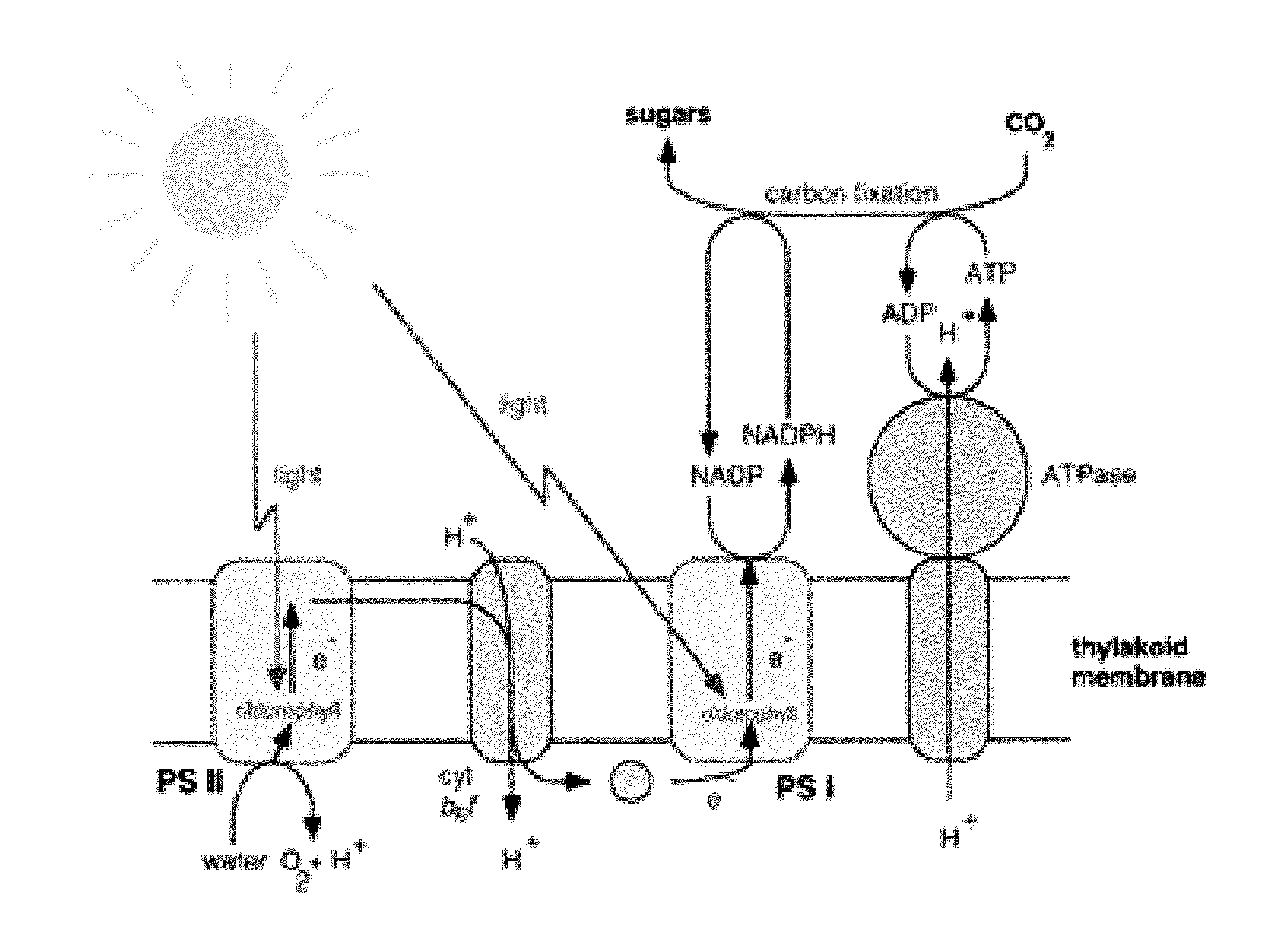
[0024]This current is then stored or directly utilized by a reservoir which is used for the continuous harvesting of hydrogen and oxygen from a flowing fluid comprised of photosynthetic material in a growth medium exposed to sun or artificial light through a light delivery device comprised of a cathode and separated by a specifically designed membrane from an anode which abuts to a hydrogen collection chamber or cavity. The gases are recovered through a porting system which captures the gases for utilization in fuel cells or other end use. The use of flowing fluids mitigates heat build up and flocculation of the biomass. A method for increasing gas production utilizing pH modifiers can be re-used in the overall cultivation system.

Problems solved by technology

Other methods, such as sulfur deprivation, do release hydrogen, but have not proven to be viable as one has to then recombine sulfur to ensure sustained growth.
While chemical modification can result in the creation of hydrogen, such processes are constrained as large-scale production methods due to difficulties in removing the chemicals as part of an integrated production system.
The bases and acids flocculate the biomass rendering it useless for further growth and contaminate the growth medium for reuse.
Thus, there are significant ongoing difficulties in obtaining hydrogen from biomass.
Tapping the energy as formed into carbohydrate leads to another reduction in the theoretical efficiency.
One unmet challenge has been to produce hydrogen and oxygen from photosynthetically generated biomass, without harsh chemical alteration, genetic modification, or combined approaches, such as prokaryote and eukaryote using the power of sunlight as the preferred embodiment.
Another challenge has been the creation of a method of generating current to power the system when there is low sunlight or in the nocturnal cycle.
Present systems fail to provide scalability and low cost and cannot be incorporated into a system that continuously produces these valuable gaseous byproducts as part of a grow system where other valuable products are generated such as food and fuels.

Method used


Image

  • Bio-Energy Reactor
  • Bio-Energy Reactor
  • Bio-Energy Reactor

Examples


example

[0068]H2 / O2 production rate was measured when the reservoir was covered with a black cover to replicate an algae dark cycle, as follows:

Start Time: 10:00 AM Bio Type: Nanochloropsis salt water species

Dry Cell Voltage: 24.3 mv Ambient Temperature: 70.7 F Bio pH: 8.88

[0069]Bio ORP: −056 Wet Cell Starting Voltage: 23.3 mv & rising

Power Input: Volts: 3.7 Amps: 0.216 Duration: 30 seconds

Starting Voltage in Cell after Input: 0.848 mv

Dark Duration of Operation: 10 AM to 2 PM / 4 hours

Readings:

[0070]

10:00 AM (start): 68 MicromolesCell Voltage:.251 mv10:30 AM132 MicromolesCell Voltage:.179 mv11:00 AM132 MicromolesCell Voltage:.134 mv11:30 AM122 MicromolesCell Voltage:.134 mv12:00 PM112 MicromolesCell Voltage:.112 mv12:30 PM102 MicromolesCell Voltage:.090 mv 1:00 PM 84 MicromolesCell Voltage:.076 mv 1:30 PM 74 MicromolesCell Voltage:.071 mv 2:00 PM 68 MicromolesCell Voltage:.064 mvEnding Hydrogen 68 MicromolesEnding Cell Voltage:.064 mvMicromoles:

[0071]Test 3:

[0072]H2 / O2 production rate were me...


PUM

PropertyMeasurementUnit
cell voltageaaaaaaaaaa
lengthaaaaaaaaaa
energyaaaaaaaaaa

Abstract

A system includes an ionic exchange conduit through which a flow of photosynthetic biomass is drawn capturing an electrical charge which is used to alternately power a photonic activated reservoir housing a living photosynthetic biomass suspended in a flowing liquid medium which self generates an electrical charge as it migrates towards and through a cathode separated from an anode by a membrane. Upon electrical transfer through the circuit an electrolysis process begins and releases hydrogen and oxygen into enclosed atmosphere chambers where these separated gases can be captured for use in a fuel cell.

Description

CROSS-REFERENCE TO RELATED APPLICATIONS[0001]This application claims the benefit of U.S. Provisional Application No. 61 / 356,435 filed Jun. 18, 2010, which is incorporated by reference herein in its entirety.BACKGROUND OF THE INVENTION[0002]1. Field of the Invention[0003]The invention relates to the production of gases from biomass and solar energy.[0004]2. Background and Related Art[0005]Implementation of the invention relates to altering the electrical properties of fluids while in a transition phase flowing through a specifically designed tube and capturing and storing electrolytic generated energy. This current is drawn and utilized to power a modified photonic galvanic cell during nighttime and clouded days, thereby increasing the production of electrolytic generated elemental hydrogen and oxygen which can be used in a fuel cell.[0006]A photosynthetic dependant living organism biomass suspended in a life supporting liquid environment depends upon an internal electrical charge as...

Claims


Application Information

Patent Timeline
Patent Type & Authority Applications(United States)
IPC IPC(8): C25B1/02C25B9/08C25B9/00C25B9/19
CPCC25B1/003C25B1/55
Inventor ECKELBERRY, NICHOLASGREEN, MICHAEL
Owner ENNESYS
Learn More