Mold for Making a Membrane for Use with a Flow Control System for a Micropump

a flow control system and valve membrane technology, applied in the direction of manufacturing tools, machines/engines, positive displacement liquid engines, etc., can solve the problems of limiting the scope of application to affecting the use of silicon material cost and related fabrication issues, and affecting the use of large and bulky drug delivery systems. , to achieve the effect of convenient maintenance and use, low manufacturing cost and convenient manufacturing

Inactive Publication Date: 2011-12-22
PICOLIFE TECH
View PDF28 Cites 11 Cited by
  • Summary
  • Abstract
  • Description
  • Claims
  • Application Information

AI Technical Summary

Benefits of technology

[0031]Thus, it is an object of the present disclosure to provide, in combination with the other features and advantages disclosed herein, a mold that facilitates consistent manufacture of the small valve membrane used to provide the improved flow system disclosed herein.
[0032]Yet another object of the present disclosure is to provide, in combination with the other features and advantages disclosed herein, a mold that has a minimum of parts constructed and arranged to work with one another to aid in the construction of the small valve membrane used to provide the improved flow system disclosed herein.
[0033]Still a further object of the present disclosure is to provide, in combination with the other features and advantages disclosed herein, a mold that is made to fine tolerances necessary to aid in the construction of the small valve membrane used to provide the improved flow

Problems solved by technology

Micropumps are one of the main components of these systems and are often the limiting factor for size, weight and cost.
However, the size of the electric motors necessary for delivering the desired forces prevents miniaturization below the 40-50 mm range.
This severely limits the scope of applications to large and bulky drug delivery systems.
However, the material cost of silicon and related fabrication issues burden its use.
However, the PDMS pumps described are based on expensive microfabrication techniques, which require costly equipment that utilizes an inherently slow process.
This limits the ability for manufacturers to mass-produce these types of pumps.
They were successful in reducing manufacturing costs but not to the point desired for disposable systems.
In the case of piezoelectric actuators, piezoelectric materials are expensive and they require high operating voltages.
This requires the use of specialized, expensive; and bulky electronics, which is especially difficult to incorporate in embedded applications.
In the case of electromagnetic actuators, an expensive and bulky coil is required inside the pump.
In both cases, electrodes and supply wiring are needed in the pump body itself, which increases the volume and price of the pump.
Unfortunately, the relatively high cost of micropumps today prevents disposable use, which strongly limits the scope of their applications.
This often leads to a lack of reproducibility and a lack of flow rate predictability.
As a result, the ability to supply precise flow rates and doses is severely impeded making them poorly suited for applications such as drug delivery.
Thus, a problem associated with d

Method used


Image

  • Mold for Making a Membrane for Use with a Flow Control System for a Micropump
  • Mold for Making a Membrane for Use with a Flow Control System for a Micropump
  • Mold for Making a Membrane for Use with a Flow Control System for a Micropump

Examples


Embodiment Construction

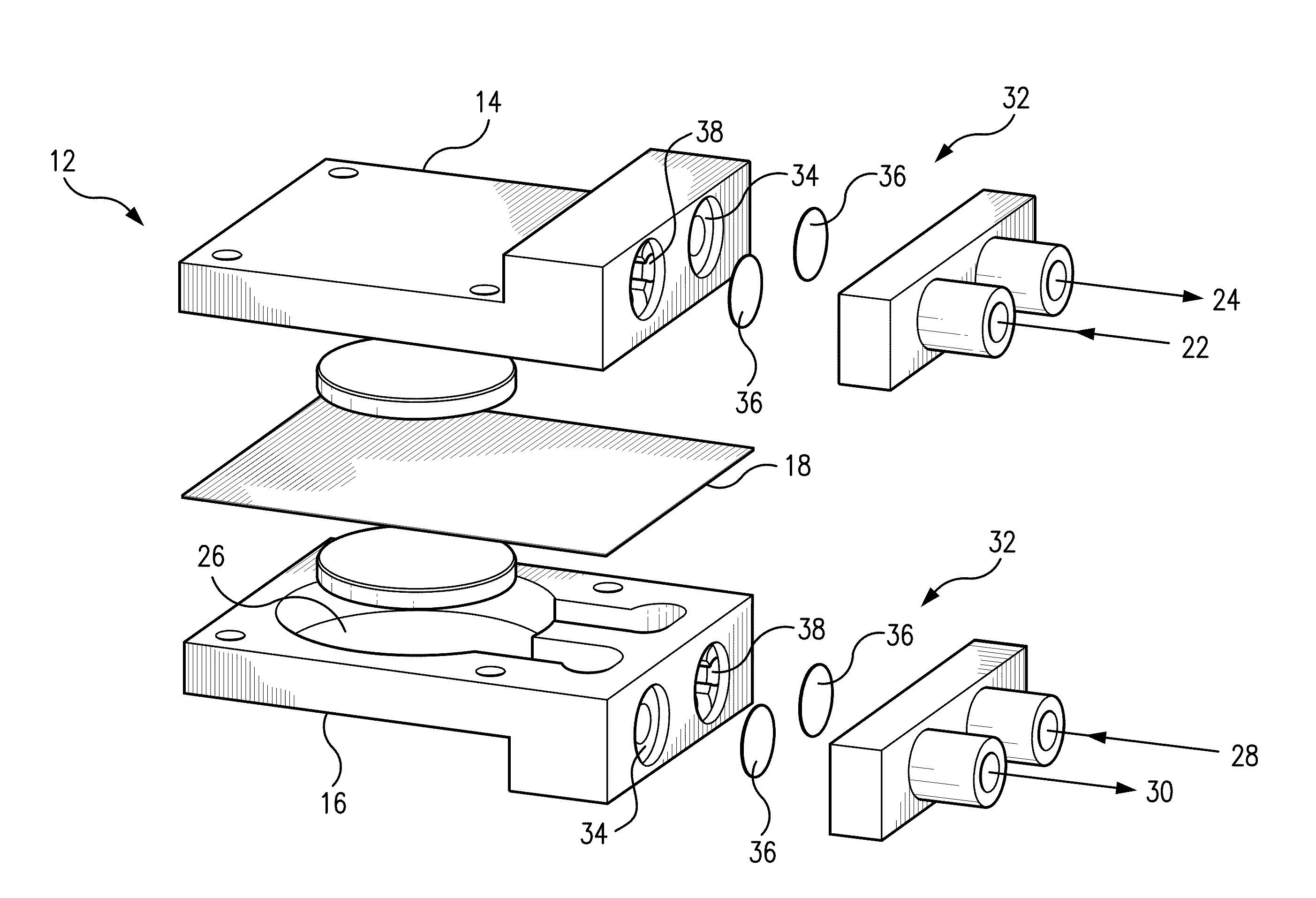
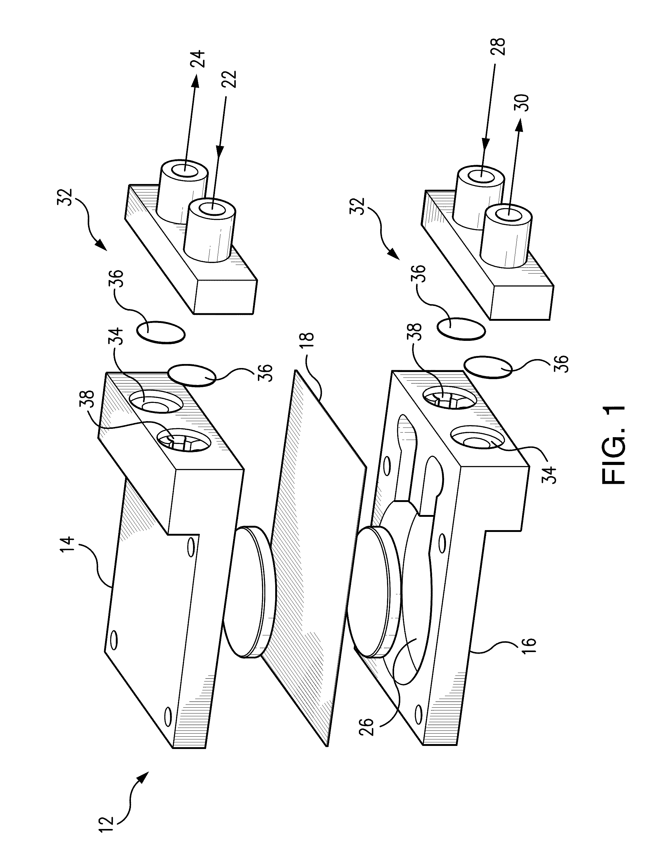
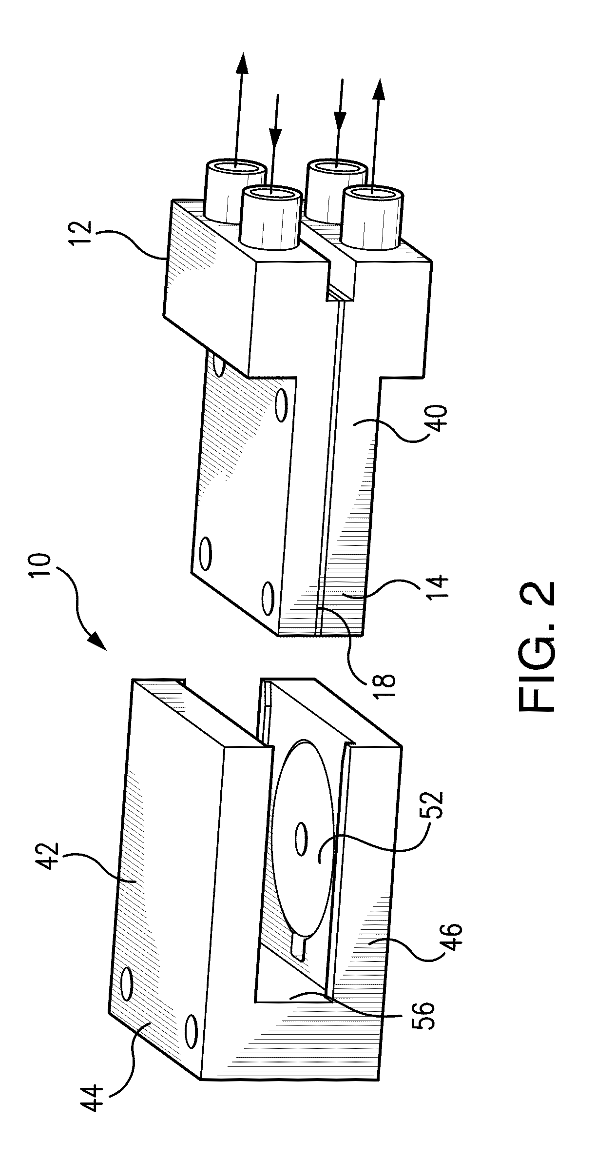
[0075]Referring now to FIGS. 1 and 2, the micropump 10 of the present disclosure includes a pump assembly 12 having a first pump body 14, a second pump body 16 and a flexible membrane 18 disposed therebetween. The first pump body 14 defines a first body flow path and includes a first chamber 20 (shown in FIG. 4). The first pump body 14 further includes a first inlet 22 and a first outlet 24 in fluid communication with the first chamber. Likewise, the second pump body 16 defines a second body flow path and includes a second chamber 26. The second pump body 16 further includes a second inlet 28 and a second outlet 30 in fluid communication with the second chamber 26.

[0076]Several proposed actuation mechanisms for micropumps have been reported already, mainly including piezoelectric, electrostatic, electromagnetic, and thermo-pneumatic and shape memory alloy, etc. The majority of the micropumps employ piezoelectric or electrostatic actuation, which operate at a relatively high frequenc...


PUM

PropertyMeasurementUnit
Lengthaaaaaaaaaa
Lengthaaaaaaaaaa
Lengthaaaaaaaaaa

Abstract

A mold for making a membrane having a reinforcement annulus configured to be received within a flow control system for use with a micropump is disclosed. The mold has a female body portion, a male body portion and a body support member. The female body portion has a cylindrical elongate lower portion extending along an axis and having a diameter D, and a centered, concave upper face having substantially the same diameter D and having a radius of curvature R. The upper face is oriented substantially perpendicularly to the axis of the elongate lower portion and extends therefrom. The male body portion has a cylindrical elongate upper portion having a lower terminus and extending along an axis. The upper portion thereof has a diameter substantially equal to D. The male body portion further has a central cylindrical portion having a height H and extending from the lower terminus along the axis of the upper portion. The central portion has a diameter of D-G, wherein G is the annular thickness of a spacing gap extending radially outward from the central portion. The male body portion further has a centered, convex lower face having a diameter substantially equal to D-G, a radius of curvature substantially equal to R and being oriented substantially perpendicularly to the axis of the elongate upper portion. The body portion support member has a generally elongated, tubular configuration and further has an inner diameter just slightly greater than D. The body portion support member is thereby configured to receive at least a portion of the female body portion and at least a portion of the male body portion, so that the female and male body portions can be maintained along the same axis. In this fashion, the convex face and concave face are positioned cooperatively to effect manufacture of the membrane having a reinforcement annulus configured to be received within a flow control system for use with a micropump.

Description

CROSS REFERENCE TO RELATED APPLICATIONS[0001]This application is a continuation-in-part of International Application No. PCT / US / 059020, filed Sep. 30, 2009, which is herein incorporated in its entirety and which in turn claims priority to U.S. provisional patent application Ser. No. 61 / 152,165, filed Feb. 12, 2009. This application also claims priority to U.S. provisional patent application Ser. No. 61 / 448,050, filed Mar. 1, 2011.FIELD OF THE INVENTION[0002]The present disclosure relates to a mold for making a valve membrane for use with a flow control system for a micropump. In particular, the present disclosure relates to a micropump including a magnetically actuated membrane to transfer fluids for handling small fluid volumes, and includes a mold used for making a valve membrane used with an innovative flow control system.BACKGROUND OF THE INVENTION[0003]The present disclosure relates to a mold for making a valve membrane for use with a flow control system for a micropump. In par...

Claims


Application Information

Patent Timeline
IPC IPC(8): B28B7/02B23P13/00
CPCY10T29/49996F04B43/043A61M5/16804A61M2205/0244A61M39/24A61M5/1422A61M5/14224A61M2039/2453Y10T137/7879Y10T137/86002Y10T137/86019
Inventor AMIROUCHE, FARIDCANTWELL, MATTHEW
Owner PICOLIFE TECH
Why Eureka
Try Eureka