Bi-layered bone-like scaffolds

Active Publication Date: 2011-12-22
BOARD OF RGT THE UNIV OF TEXAS SYST
View PDF3 Cites 71 Cited by
  • Summary
  • Abstract
  • Description
  • Claims
  • Application Information

AI Technical Summary

Benefits of technology

[0016]A microchannel may be interconnected with one or more other microchannels or with one or more micropores. In embodiments of the present invention that possess an outer cortical shell and an inner trabecular core, the outer cortical shell and/or inner trabecular core may possess one or more microchannels or micropores. Microchannels and/or micropores of the outer cortical layer may be connected to microchannels and/or micropores of the inner travecular core. An interconnected structur

Problems solved by technology

However, the ideal material and fabrication technique for optimal bone tissue regeneration has yet to be identified.
While current materials and techniques have met with varying successes, each material and/or technique exhibits limitations that must be addressed.
In addition, there is an overall lack of success in bringing these technologies to the clinic, especially for the reconstruction and restoration of large bone defects.
Although the use of biodegradable polymer scaff

Method used


Image

  • Bi-layered bone-like scaffolds
  • Bi-layered bone-like scaffolds
  • Bi-layered bone-like scaffolds

Examples


example 1

Procedure for Porous Calcium Phosphate Scaffold Fabrication

[0111]1.1 Polymeric sponge template preparation

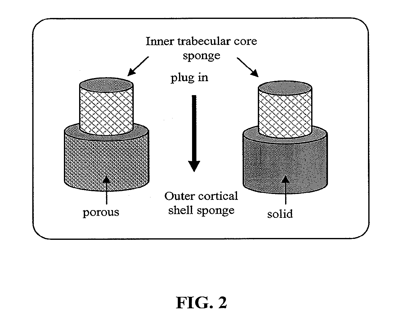
[0112]Selection of the template material: A polyurethane (PU) sponge template is used to produce uniform interconnected porous calcium phosphate scaffolds. This sponge is used to provide the primary structure for the formation of the scaffold struts as well as the formation of secondary microchannels within the scaffold struts. The polyurethane sponge template chosen may range from 45 pores per inch (ppi) to 80 ppi for the inner trabecular core, depending on the final desired pore size. The pore sizes in the inner trabecular core may range from 150 μm to 800 μm after sintering to allow bone cell migration, blood vessel vascularization, and nutrient supply. Additionally, the 80 ppi to 100 ppi polyurethane sponge template or solid calcium phosphate ceramics (with channels and / or pores produced by slip casting) may be chosen for the outer cortical shell, depending on the final desi...

example 2

Examples of Fabricated Hydroxyapatite Scaffolds

[0126]Using the process described in Example 1, an example on how this technology is used to fabricate hydroxyapatite scaffolds coated with silver-doped hydroxyapatite is as follows:

2.1 Polymetric sponge template preparation for bi-layered porous scaffold fabrication:

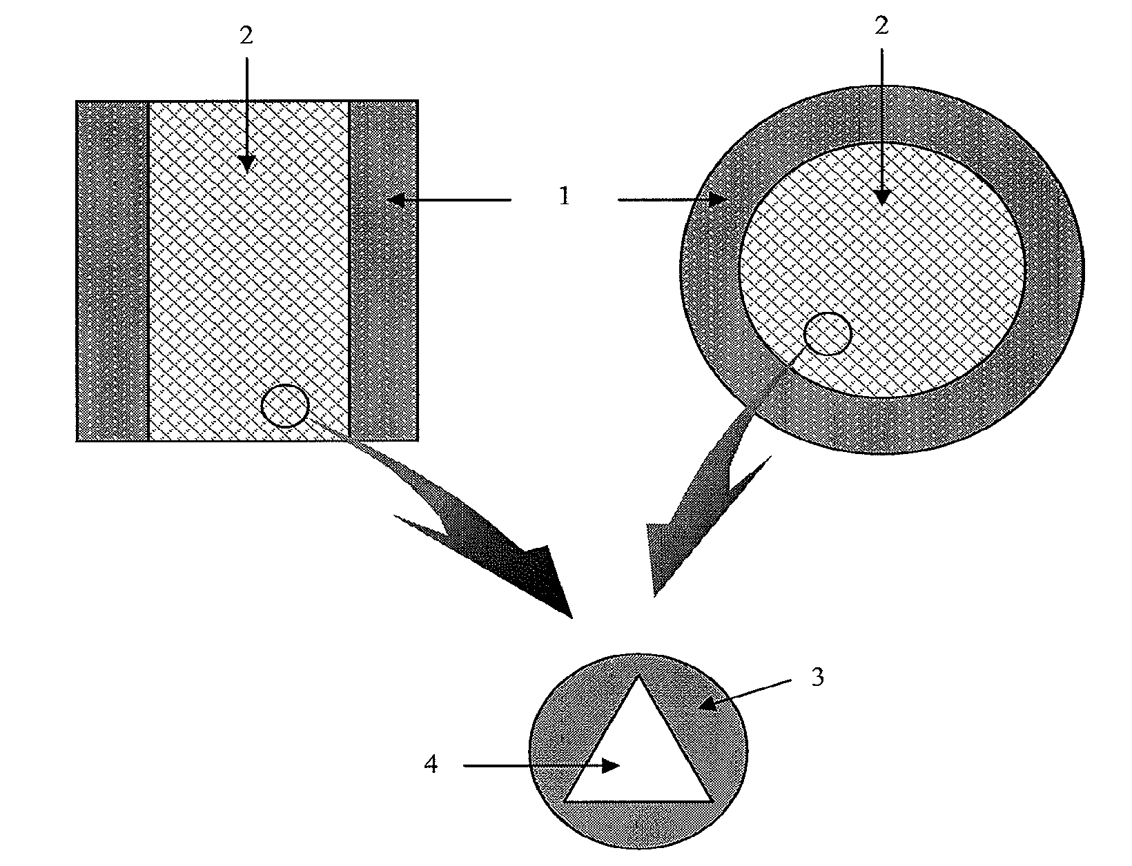
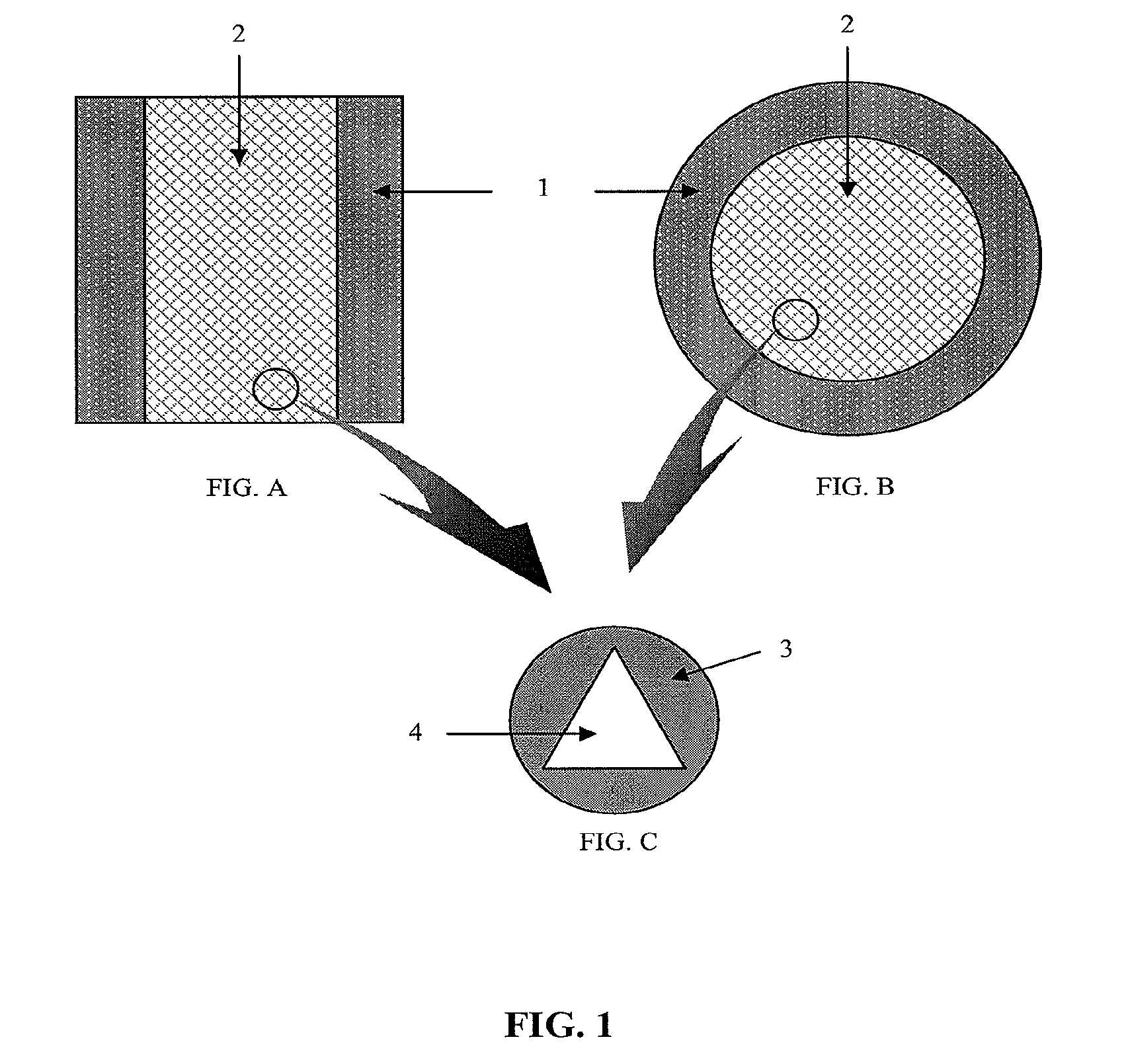
[0127]A 60 ppi (pore per inch) polyurethane sponge template is chosen for trabecular core fabrication and the 100 ppi polyurethane sponge template is chosen for outer cortical shell fabrication. The polyurethane sponge template for the trabecular core is cut to a shape of a solid cylinder with a length of 36 mm and a diameter of 28 mm. The polyurethane sponge template for the outer cortical shell is cut to resemble a cylindrical pipe and is hollow core in the middle. Dimension for the polyurethane sponge template for the outer cortical shell is 36 mm in length, with an outer diameter of 30 mm and an inner diameter of 28 mm, thereby having a 2 mm wall thickness. These polyur...

example 3

Examples of Properties of Hydroxyapatite Scaffolds

[0152]The materials discussed below were prepared by the methods of Example 1 and Example 2.

3.1 Polymeric sponge template

[0153]After 20 minutes of treating the polymeric sponge template with 10% sodium hydroxide, the surface of the sponge is changed from smooth to rough and is more hydrophilic. As shown in FIG. 7, the shape of the originally cut sponge remains intact, together with its elastic property.

3.2 First time calcium phosphate coated, dried and sintered scaffold

[0154]After immersing the treated polyurethane sponge template in a first time coating slurry followed by drying at 27° C. in a 80% humidity environment for 60 hours, the bi-layered calcium phosphate coated sponge template appears hardened. The coated surface also appears dense and smooth, with only a few cracks observed. Additionally, the scaffold shrinks by 8%.

[0155]After sintering the coated sponge using a 8-step sintering profile shown in FIG. 3, the resulting scaf...


PUM

PropertyMeasurementUnit
Pore sizeaaaaaaaaaa
Pore sizeaaaaaaaaaa
Pore sizeaaaaaaaaaa

Abstract

Disclosed are biomedical scaffolds that may be used, for example, for treatment of bone diseases and bone repair. Methods of preparing such scaffolds are also disclosed. These scaffolds permit nutrient and ion flow such that bone regeneration in the area surrounding the scaffold is promoted. Also disclosed are kits that include the scaffolds set forth herein.

Description

BACKGROUND OF THE INVENTION[0001]The present application claims the benefit of priority to U.S. Provisional Patent Application Ser. No. 60 / 955,014, filed Aug. 9, 2007, the entire contents of which is hereby specifically incorporated by reference.[0002]1. Field of the Invention[0003]The present invention generally relates to the fields of biomedical scaffolds, and methods of treating disease or disorders in a subject that involve implantation of the scaffolds set forth herein.[0004]2. Description of Related Art[0005]Considerable research has been reported over the last decade in the use of polymeric and ceramic biomaterials for producing scaffolds. However, the ideal material and fabrication technique for optimal bone tissue regeneration has yet to be identified. While current materials and techniques have met with varying successes, each material and / or technique exhibits limitations that must be addressed. In addition, there is an overall lack of success in bringing these technolog...

Claims


Application Information

Patent Timeline
IPC IPC(8): A61F2/28A61F2/02
CPCA61F2/08A61L27/56A61F2/2803A61F2/2875A61F2/30756A61F2/30767A61F2/30771A61F2/44A61F2/4644A61F2002/2817A61F2002/2825A61F2002/2839A61F2002/2871A61F2002/2892A61F2002/2896A61F2002/30011A61F2002/30062A61F2002/3024A61F2002/30677A61F2002/307A61F2002/30701A61F2002/30703A61F2002/30705A61F2002/3092A61F2002/30929A61F2002/30957A61F2002/30968A61F2002/30971A61F2210/0004A61F2230/0069A61F2250/0023A61F2250/0081A61F2310/00083A61F2310/00113A61F2310/00293A61F2310/00473A61F2310/0052A61F2310/00796A61L27/12A61L27/425A61L27/46A61F2/28A61F2002/30235
Inventor OH, DANIEL SUNHOONG, ANSON
Owner BOARD OF RGT THE UNIV OF TEXAS SYST
Why Eureka
Try Eureka