

Biocompatible Membrane and Process for Producing the Same
a biocompatible membrane and process technology, applied in dental surgery, impression caps, prostheses, etc., can solve the problems of limited application of tissue regeneration methods using such a gtr membrane, difficult application of such a conventional gtr membrane to periodontal tissue, and ordinary doctors have not been able to utilize gbr membranes. , to achieve the effect of short time, low cost and no production steps
- Summary
- Abstract
- Description
- Claims
- Application Information
AI Technical Summary
Benefits of technology
Problems solved by technology
Method used
Image

Examples
example 1
[0072] A fine powder (mean particle diameter: 100 μm) was obtained by emulsifying polylactic acid and removing the solvent. The target region for periodontal tissue regeneration treatment was subjected to CT scanning to obtain three-dimensional digital data of the treatment region. Based on the data, the design of a configuration suitable for the treatment was prepared, then subjected to data processing and used as three-dimensional lamination forming data. The above-obtained polylactic powder was placed in a powder lamination forming machine. More specifically, using a movable container, the fine powder in an amount appropriate for a specific thickness was supplied to the worktable of the machine at 155° C. in a flat manner, and the fine powder was irradiated with a carbon dioxide laser (50 W) according to cross-sectional slices of the 3-dimensional configuration to fix the specific thickness of the fine powder by sintering or fusion. By repeating this procedure and removing excess...
example 2
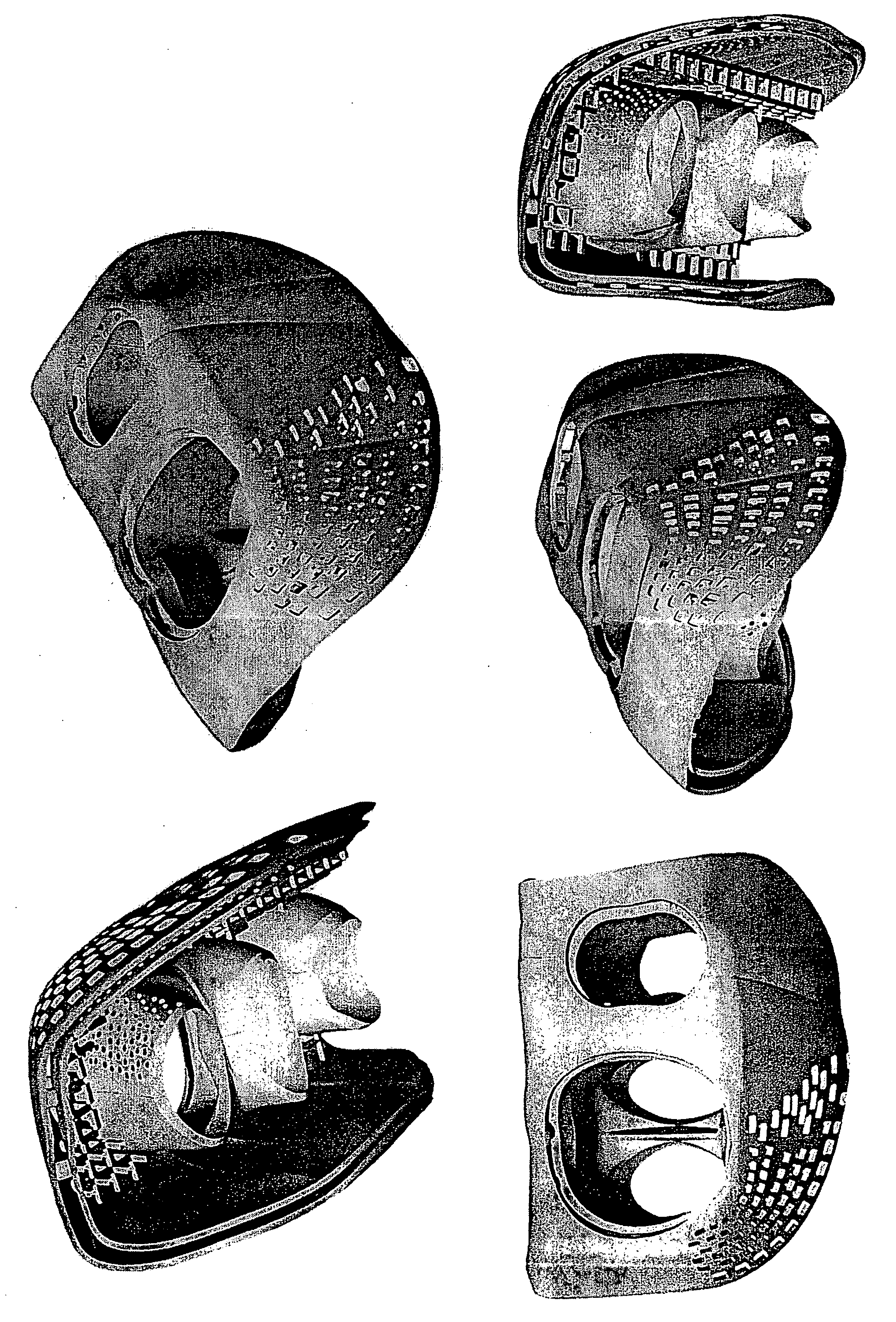
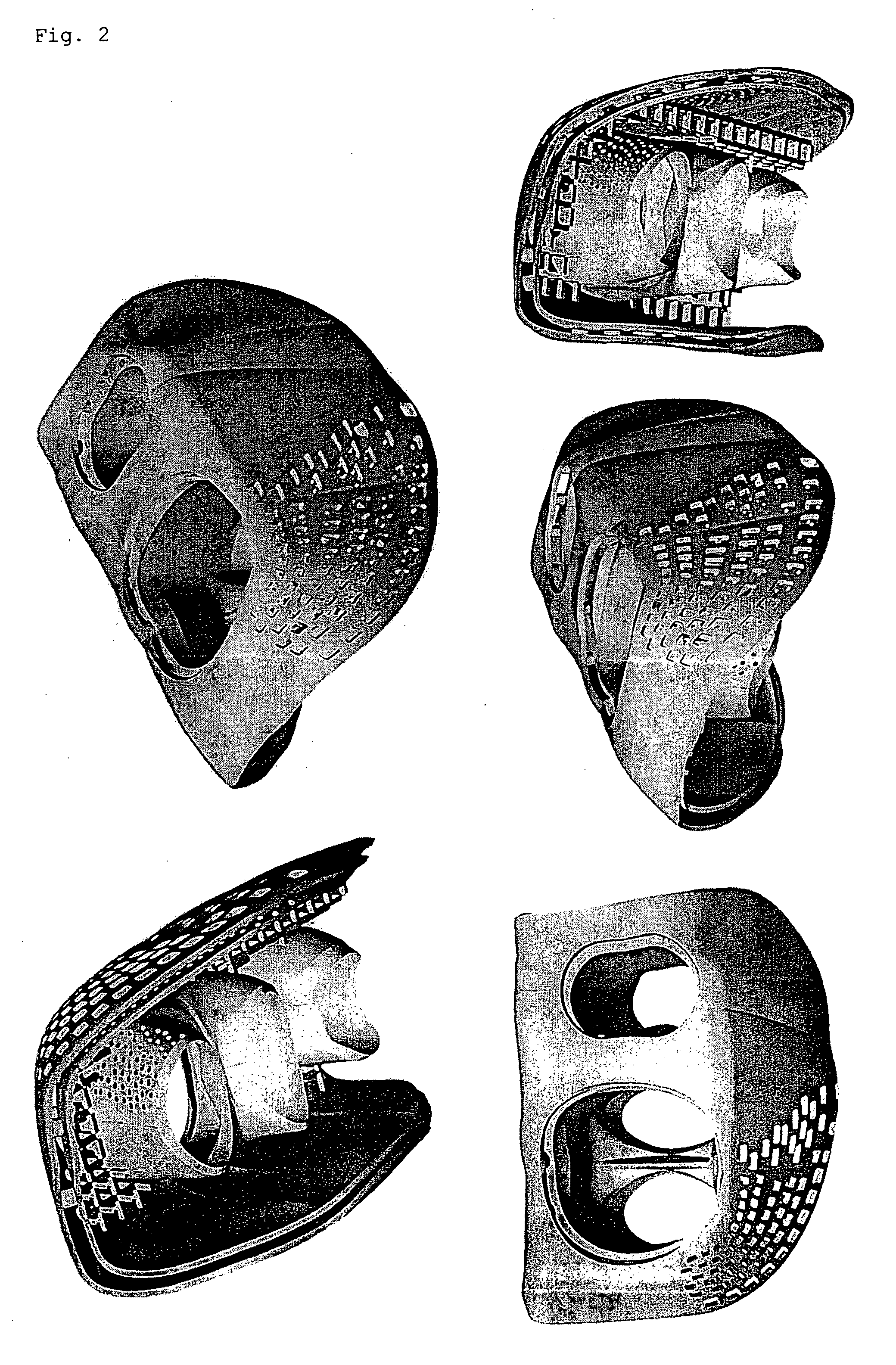
[0073] The target region for periodontal tissue regeneration treatment was subjected to CT scanning to prepare three-dimensional digital data of the treatment region. Based on this data, two differently shaped models that fit the treatment region, i.e., an inner layer model with circular holes and cylindrical spacers, and an outer layer model with rectangular holes, were prepared using appropriate resins. A polylactic acid fine powder was electrostatically applied thereto and heated to provide a tissue regeneration membrane.
example 3
[0074] A fine powder (mean particle diameter: 100 μm) was obtained by emulsifying polylactic acid and removing the solvent. The target region for implant treatment was subjected to CT scanning to obtain three-dimensional digital data of the treatment region. Based on the data, the design of a configuration suitable for the treatment was prepared, then subjected to data processing and used as three-dimensional lamination forming data. The above-obtained polylactic powder was placed in a powder lamination forming machine. More specifically, using a movable container, the fine powder in an amount appropriate for a specific thickness was supplied to the worktable of the machine at 155° C. in a flat manner, and the fine powder was irradiated with a carbon dioxide laser (50 W) according to cross-sectional slices of the 3-dimensional configuration to fix the specific thickness of the fine powder by sintering or fusion. By repeating this procedure and removing excess fine powder using a bru...
PUM
| Property | Measurement | Unit |
|---|---|---|
| thickness | aaaaa | aaaaa |
| porosity | aaaaa | aaaaa |
| pore size | aaaaa | aaaaa |
Abstract
Description
Claims
Application Information