

Digital Hybrid V2 Control for Buck Converters
- Summary
- Abstract
- Description
- Claims
- Application Information
AI Technical Summary
Benefits of technology
Problems solved by technology
Method used
Image

Examples
Embodiment Construction
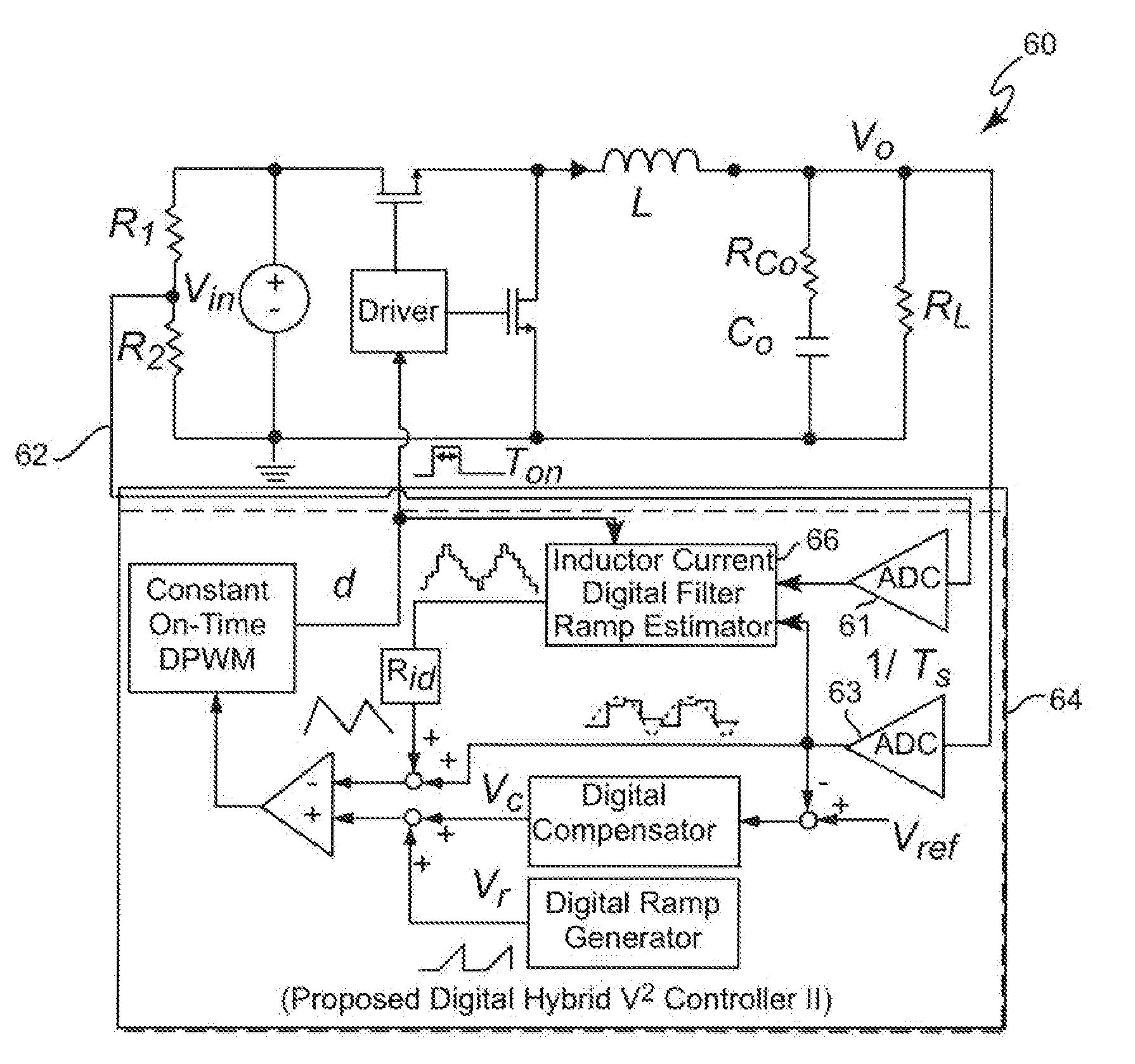
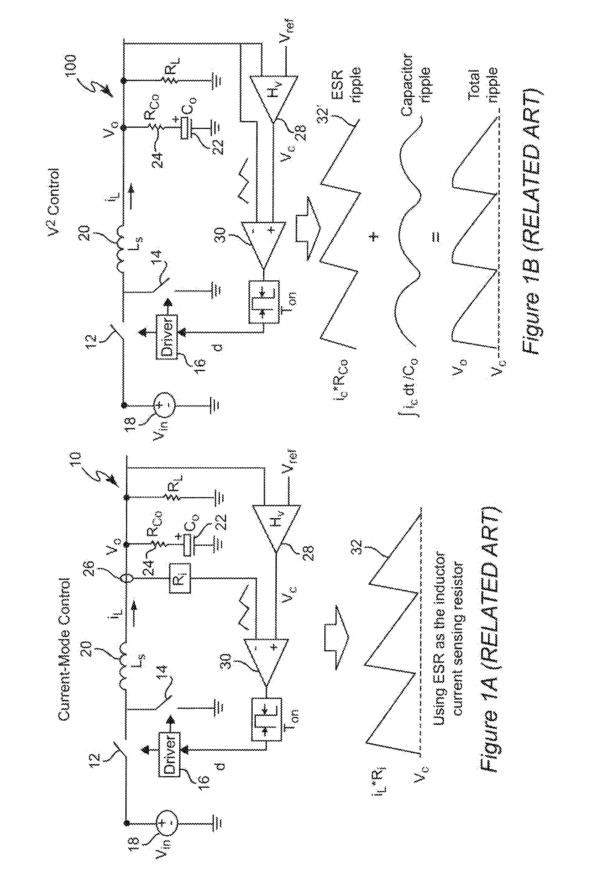
[0028]Referring now to the drawings, and more particularly to FIGS. 1A and 1B, schematic diagrams of buck converters respectively having current-mode control and V2 control are shown. These schematic diagrams are arranged to facilitate an understanding of and appreciation for the invention and no portion of either Figure or FIGS. 2A and 2B is admitted to be prior art in regard to the present invention. It should also be understood that while the invention will be described in connection with a buck converter, the invention is also applicable to other switching power converter topologies. Similarly, for simplicity and to facilitate conveying an understanding of the invention and the problems addressed by it, the invention will be described assuming a constant on-time switching arrangement although the invention is not limited to such an application and constant off-time, constant frequency or other switching schemes or any combination thereof can be employed in the practice of the in...
PUM
 Abstract
Description
Claims
Application Information