Surface-emitting laser light source using two-dimensional photonic crystal

a laser light source and photonic crystal technology, applied in the direction of lasers, semiconductor laser structural details, semiconductor lasers, etc., can solve the problems of reducing the efficiency of laser beams, unable to provide rotational symmetry in the lattice point, and the intensity of light to be extracted in the direction perpendicular to the surface cannot be symmetrically symmetric, so as to achieve high efficiency

Active Publication Date: 2012-01-05
KYOTO UNIV +1
View PDF5 Cites 13 Cited by
  • Summary
  • Abstract
  • Description
  • Claims
  • Application Information

AI Technical Summary

Problems solved by technology

Thus, the anti-symmetric mode of light cannot be extracted in the direction perpendicular to the surface.
However, even in this case, the intensity of light to be extracted in the direction perpendicular to the surface is weakened by receiving the effects of interference.
This method does not provide rotational symmetry in the lattice point, which means the crystal as a whole does not have rotational symmetry.

Method used


Image

  • Surface-emitting laser light source using two-dimensional photonic crystal
  • Surface-emitting laser light source using two-dimensional photonic crystal
  • Surface-emitting laser light source using two-dimensional photonic crystal

Examples


embodiments

(1) First Embodiment

One Example of the First Aspect of the Surface-Emitting Laser

[0091]As a first embodiment of the laser light source according to the present invention, one example of the first aspect of the surface-emitting laser light is explained referring to FIGS. 3 to 5.

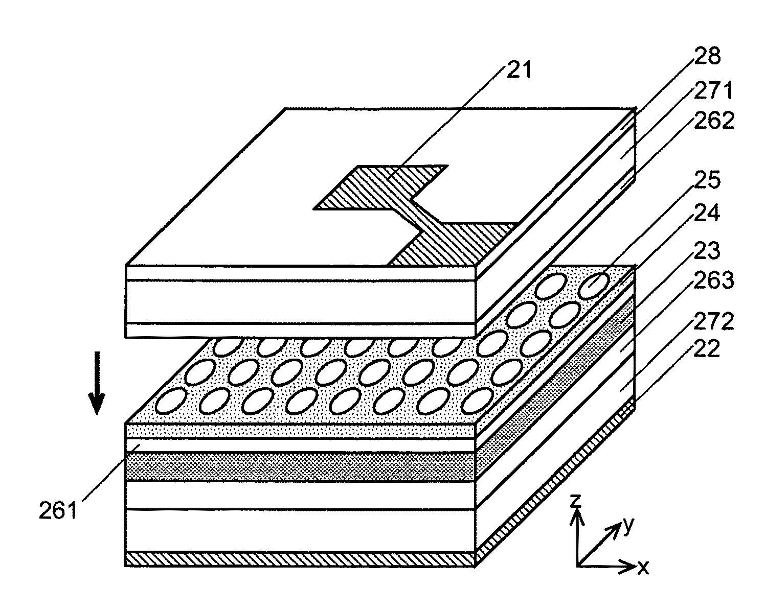
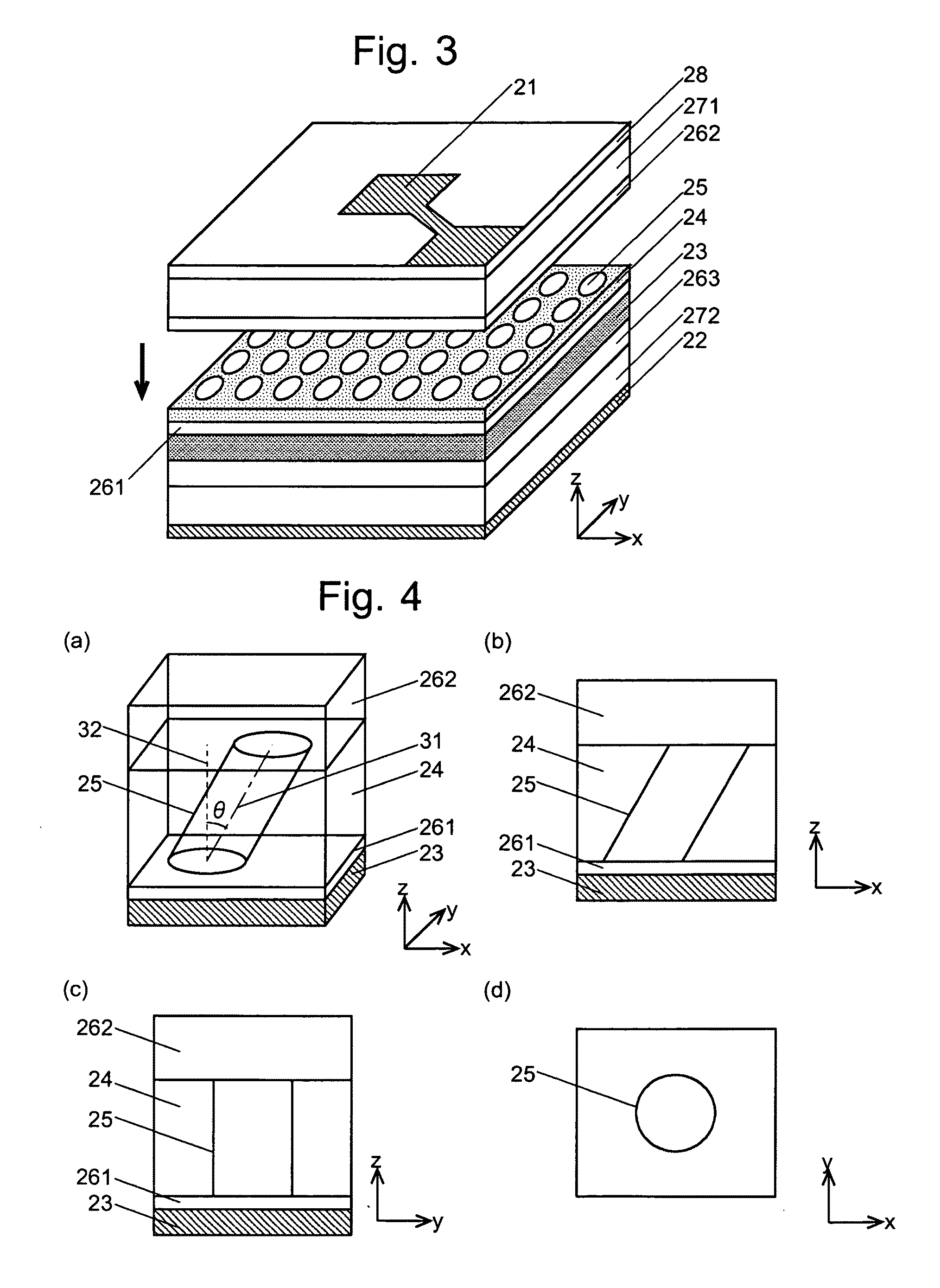
[0092]In the laser light source of the present embodiment as shown in FIG. 3, an active layer 23 made of Indium Gallium Arsenide (InGaAs) / Gallium Arsenide (GaAs) and having multiple quantum wells (MQW) is provided between an anode 21 and a cathode 22. A two-dimensional photonic crystal layer 24 made of p-type GaAs is formed on the active layer 23 via a spacer layer 261, which is also made of p-type GaAs. The two-dimensional photonic crystal layer 24 includes a plate member having holes 25 periodically arranged in a square lattice pattern. The shape of the holes 25 is described later. In the example of FIG. 3, the spacer layer 261 and the two-dimensional photonic crystal layer 24 are integrally created as a sin...

second embodiment and third embodiment

(2) Second Embodiment and Third Embodiment

Other Examples of the First Aspect of the Surface-Emitting Laser

[0099]Next, the second and third embodiments of the laser light source according to the present invention are explained referring to FIGS. 6 and 7. The laser light sources in these embodiments have a structure similar to that of the laser light source of the first embodiment shown in FIG. 3 with the exception of the shape of the holes.

[0100]FIG. 6 shows the shape of a hole 45 in the second embodiment and FIG. 7 shows the shape of a hole 55 in the third embodiment. In both FIGS. 6 and 7, (a) is a perspective view, (b) is a protection view to the x-z plane, (c) is a projection view to the y-z plane, and (d) is a sectional view (or plan view) on the surface of the two-dimensional photonic crystal layer 24 disposed on the spacer layer 262. As in the case of FIG. 3, a large number of holes having the same shape are actually arranged in a square lattice pattern in the two-dimensional ...

fourth embodiment

(4) Fourth Embodiment

Second Aspect of the Surface-Emitting Laser

[0109]As a fourth embodiment of the present invention, FIGS. 13 to 19 are used to explain an example of the second aspect of the surface-emitting laser. FIG. 13 is a perspective view showing a laser light source of the present embodiment. This laser light source has a structure similar to that of the laser light source of the first embodiment except for a two-dimensional photonic crystal layer 74. The structure of the two-dimensional photonic crystal layer 74 is now explained.

[0110]FIG. 14(a) is a top view of the two-dimensional photonic crystal layer 74. The two-dimensional photonic crystal layer 74 is created from a slab-shaped matrix body made of p-type GaAs with a thickness of 130 nm in which modified refractive index region groups 75 are arranged in a square lattice pattern with a period of 285 nm. FIGS. 14(b) and 14(c) are a top view and a longitudinal sectional view of one of the modified refractive index region ...


PUM


Abstract

The present invention intends to provide a surface-emitting laser light source using a two-dimensional photonic crystal in which the efficiency of extracting light in a direction perpendicular to the surface is high. In a laser light source provided with a two-dimensional photonic crystal layer created from a plate-shaped matrix body in which a large number of holes are periodically arranged and an active layer arranged on one side of the two-dimensional photonic crystal layer, the holes are created to be columnar with a predetermined cross-sectional shape such as a circular shape, and the main axis of each of the columnar holes is tilted to a surface of the matrix body. When provided with this two-dimensional photonic crystal layer, the surface-emitting laser source using a two-dimensional photonic crystal has a Q⊥ value (i.e. a Q value in a direction perpendicular to the surface) of several thousands, which is suitable for an oscillation of laser light, and the efficiency of extracting light is high in the direction perpendicular to the surface.

Description

[0001]This is a Division of application Ser. No. 11 / 991,403 filed Apr. 4, 2008, which in turn is a National Phase of PCT / JP2006 / 317486 filed Sep. 5, 2006. The disclosure of the prior applications is hereby incorporated by reference herein in its entirety.TECHNICAL FIELD[0002]The present invention relates to a surface-emitting laser light source for emitting laser light in a direction perpendicular to the surface of a flat light source.BACKGROUND ART[0003]Conventional laser light sources include a Fabry-Perot laser light source, which uses a Fabry-Perot resonator, and a distributed feedback (DFB) laser light source, which uses a diffraction grating. These types of laser light sources produce an oscillation of laser light by amplifying light of a predetermined wavelength through resonation or diffraction.[0004]In recent years, new types of laser light sources using a photonic crystal have been developed. A photonic crystal includes a dielectric matrix body in which an artificial perio...

Claims


Application Information

Patent Timeline
Patent Type & Authority Applications(United States)
IPC IPC(8): H01S5/02H01L21/3065
CPCH01S5/0425H01S5/105H01S2301/18H01S5/18358H01S5/18308H01S5/04254H01S5/11
Inventor NODA, SUSUMUMIYAI, EIJIOHNISHI, DAI
Owner KYOTO UNIV
Why Eureka
Try Eureka