
Cover film

Active Publication Date: 2012-01-05
DENKA CO LTD
View PDF4 Cites 11 Cited by
  • Summary
  • Abstract
  • Description
  • Claims
  • Application Information

AI Technical Summary

Benefits of technology

[0020]The present invention offers a cover film that is not susceptible to “film breakage” even during high-speed peeling, and excelling in heat sealing properties, stability of peel strength and transparency.
[0021]Furthermore, the invention offers, in addition to the above properties, a cover film that is capable of suppressing the electrostatic damage that may occur as a result of the peeling.
[0034]The cover film of the present invention is capable of adequately suppressing the occurrence of “film breakage” during high-speed peeling from a carrier tape, and excels in heat sealing properties, stability of peel strength and transparency. Furthermore, the cover film of the present invention, in addition to the above properties, also suppresses electrostatic damage during peeling. Additionally, the electronic component package of the present invention which is obtained using such a cover film is particularly suited to high-speed mounting of electronic components.

Problems solved by technology

If the peel strength is too high, the cover film can tear during peeling, and if too weak, the cover film can come away from the carrier tape during storage or transport, and the electronic components contained therein may be lost.
In particular, the rapid advances in mounting speed have led to very high cover film peeling rates of 0.1 seconds per tact or less, which places great stress on the cover film during peeling.
As a result, there is a problem called “film breakage” in which the cover film is torn.
However, during the actual process of mounting electronic components, the peeling rate is faster than 300 mm per minute, and particularly when housing large connector components, they are often sealed with a peel strength close to the upper limit, as a result of which film breakage is liable to occur when peeling the cover film.
However, even with these methods, it is difficult to avoid film breakage during high-speed peeling of 100 m per minute.
However, even with this method, the stability of the peel strength after heat sealing is inadequate.
However, since metal oxides are relatively expensive, they can easily lead to increased costs, and since it is not easy to uniformly disperse metal oxides into the sealant layer, dispersion problems can cause disparities in peel strength.
Additionally, while the dispersion of surfactants into the sealant layer (see Patent Document 7) has been proposed, when an electronic component package formed of a carrier tape heat sealed by a cover film is stored for days in a high-temperature, high-humidity environment, the surfactant can migrate to the surface of the sealant layer, reducing the peel strength and causing the cover film to peel.
However, the miniaturization of electronic components has led to a demand for even higher levels of suppression of static electricity generated on the surface of the sealant layer, and the demanded performance may not be achievable.

Method used


Image

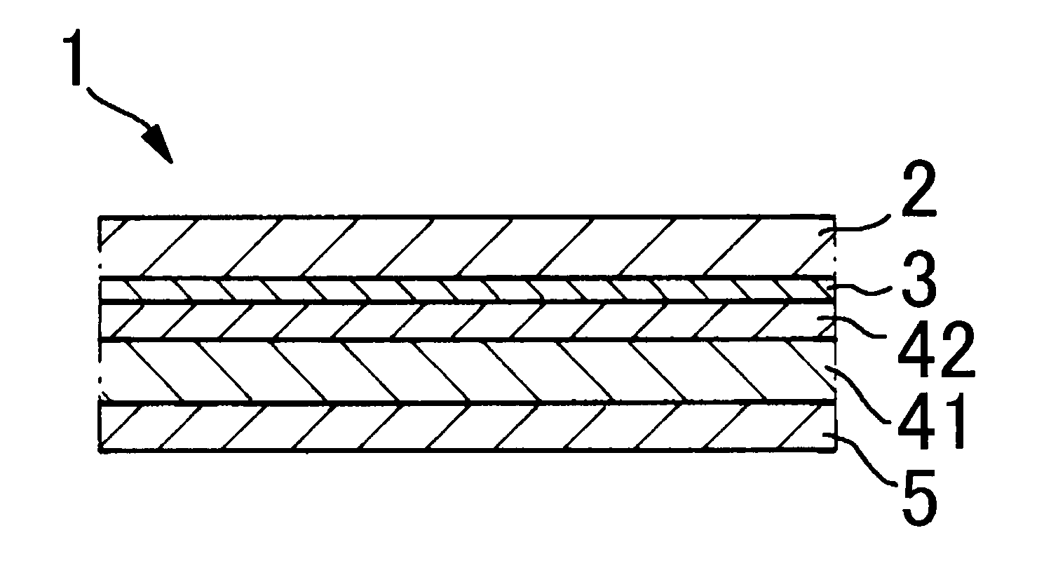
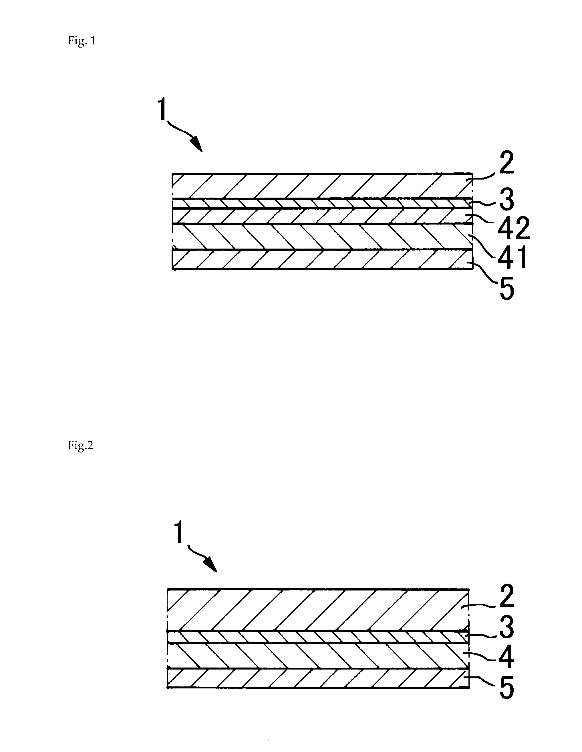
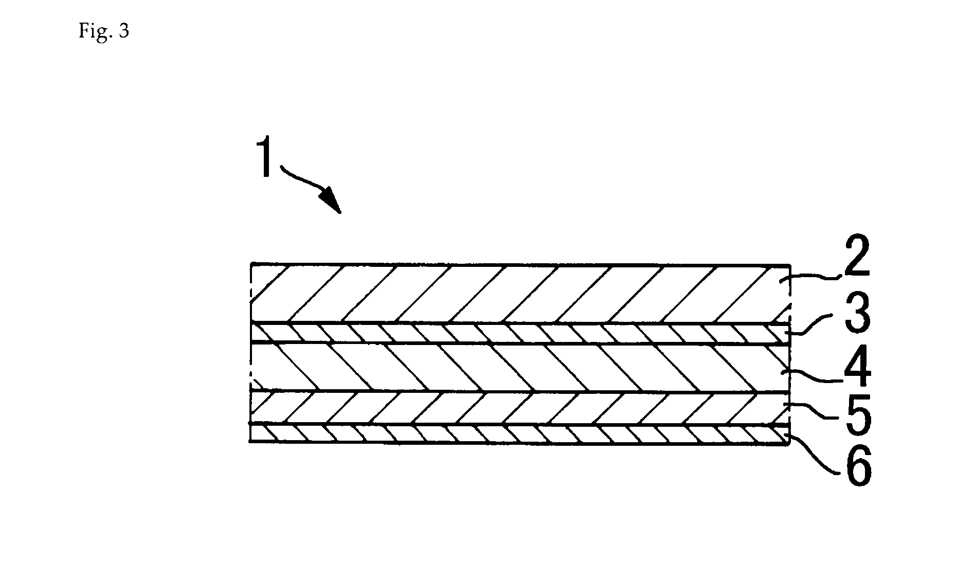
  • Cover film
  • Cover film
  • Cover film

Examples


example 1

[0095]100 parts by mass of Tuftec H1041 (Asahi Kasei Chemicals), a hydrogenated styrene-butadiene-styrene triblock copolymer and 25 parts by mass of an anti-blocking master batch “PEX ABT-16” (Tokyo Printing Ink) comprising 50 mass % low-density polyethylene, 45 mass % silica and 5 mass % talc (hereinafter referred to as “Anti-blocking Agent 1”) were pre-blended in a tumbler, then kneaded at 200 ° C. using a uniaxial extruder of diameter 40 mm to obtain a resin composition for the sealant layer at a line speed of 20 m per minute.

[0096]This resin composition for the sealant layer and a m-LLDPE “Evolue SP3010” (Prime Polymer) for a first intermediate layer were separately extruded from a uniaxial extruder, then extrusion laminated using a multi-manifold T-die, to form a two-layered film wherein the thicknesses of the sealant layer and the first intermediate layer were respectively 10 μm and 20 μm.

[0097]On the other hand, a two-solution curable polyurethane anchor coating agent was app...

example 12

[0100]A two-layered film formed of an intermediate layer (first intermediate layer) / sealant layer was prepared in the same manner as Example 1 aside from the thickness of the first intermediate layer being 30 μm.

[0101]On the other hand, a two-solution curable polyurethane anchor coating agent was applied to a biaxially stretched polyethylene terephthalate film (thickness 16 μm) constituting a substrate layer using a roll coater, and this coated surface was laminated with the intermediate layer-side surface of the above-described two-layer film by means of dry lamination to obtain a laminated film. After subjecting the sealant layer-side surface and substrate layer-side surface of the laminated film to a corona treatment, a cationic anti-static agent “SAT-6C” (Nihon Junyaku) was coated onto both surfaces of the laminated film using a gravure coater, resulting in a cover film having a substrate layer / intermediate layer / sealant layer structure.

example 19

[0103]A urethane anchor coating agent was coated to a dry thickness of about 1 μm onto the surface of a biaxially stretched polyethylene terephthalate film (thickness 25 μm) constituting the substrate layer, then m-LLDPE “Harmolex NH745N” (Japan Polyethylene) constituting the intermediate layer was extrusion coated to a thickness of 15 μm using a T-die, resulting in a two-layer film having a substrate layer / intermediate layer structure. Furthermore, as a resin constituting a sealant layer, a resin composition comprising 100 parts by mass of “Tuftec H1041” (Asahi Kasei Chemicals), a hydrogenated styrene-butadiene-styrene triblock copolymer, and 25 parts by mass of an anti-blocking master batch “PEX ABT-16” (Tokyo Printing Ink), was laminated to a thickness of 20 μm by extrusion coating onto the intermediate layer-side of this two-layer film to form a laminated film. After subjecting the sealant layer-side surface and substrate layer-side surface of the laminated film to a corona trea...


PUM

PropertyMeasurementUnit
Percent by massaaaaaaaaaa

Abstract

A cover film comprising a substrate layer, an intermediate layer comprising a resin composition containing 50% by mass or more of a metallocene linear low-density polyethylene resin having a density of 0.900 to 0.940×10³ kg / m3, and a sealant layer comprising an ethylene-type copolymerized resin containing 50 to 85% by mass of an olefin component.

Description

TECHNICAL FIELD[0001]The present invention relates to a cover film for carrier tape used in the packaging of electronic components.BACKGROUND ART[0002]The miniaturization of electronic devices has been accompanied by advances in compactness and performance of the electronic components used, and the assembly of electronic devices often involves automatically mounting the electronic components onto a printed circuit board. Generally, electronic components for surface mounting are stored and transported in the form of electronic component packages formed by encasing them in carrier tape having consecutively embossed pockets for housing the electronic components, overlaying a cover film on the tape surface of the carrier tape to form a lid material, and continuously heat sealing with a seal bar. The cover film may be of a type having a sealant layer formed of a thermoplastic resin laminated over a base material comprising a biaxially stretched polyester film.[0003]When mounting electron...

Claims


Application Information

Patent Timeline
IPC IPC(8): B65D65/40B32B27/32B32B27/36B32B27/18
CPCB32B25/14Y10T428/24612B32B27/32B32B27/322B32B27/36B32B2307/518H01L23/293H01L2924/0002B32B27/20Y10T428/31Y10T428/24942Y10T428/2826Y10T428/24355Y10T428/1352H01L2924/00B32B27/08B32B2250/24B32B2307/21B32B2307/31B32B2307/412B32B2307/546B32B2307/5825B32B2307/72B32B2307/732B32B2457/00Y10T428/31931Y10T428/31924Y10T428/31855Y10T428/31797B65D73/02B65D65/40B65D85/00
Inventor IWASAKI, TAKAYUKIFUJIMURA, TETSUOSASAKI, AKIRA
Owner DENKA CO LTD
Learn More