Cooling apparatus for a web deposition system

a technology of cooling apparatus and web, which is applied in the direction of drying solid materials, drying machines, textiles and paper, etc., can solve the problems of increasing the temperature of the web, and damage to the web, so as to increase the heat transfer and increase the heat transfer

Inactive Publication Date: 2012-01-12
AVENTA TECH INC
View PDF14 Cites 18 Cited by
  • Summary
  • Abstract
  • Description
  • Claims
  • Application Information

AI Technical Summary

Benefits of technology

[0004]In one aspect, the invention features an apparatus for cooling a web. The apparatus includes an inner cylinder and an outer cylinder. The inner cylinder has a void and is configured for coupling to a gas source. The outer cylinder has an inner surface, an outer surface to support a web, and a plurality of apertures between the inner surface and the outer surface. The outer cylinder is concentric with the inner cylinder and is configured to rotate about the inner cylinder. A gas provided to the void of the inner cylinder flows through the apertures that are adjacent to the void and passes to the outer surface of the outer cylinder to thereby increase heat transfer between the web and the outer cylinder.
[0005]In another aspect, the i

Problems solved by technology

The deposition process induces a heat load on the web, resulting in an increase in temperature.
In many applications, the increase in the temperature of the web is unacceptable.
For example, at high coating speeds and web transport rates, the heat load can cause the web to wrinkle and crease, possibly resulting in permanent damage to the web.
As the heat load is typically proportional to the deposition rate, the throughput of the deposition system is severely limited.
The thermal conductance between the web and the cooling drum affects the ability to control the temperature rise of the web during the coating process, and sets an up

Method used


Image

  • Cooling apparatus for a web deposition system
  • Cooling apparatus for a web deposition system
  • Cooling apparatus for a web deposition system

Examples


Embodiment Construction

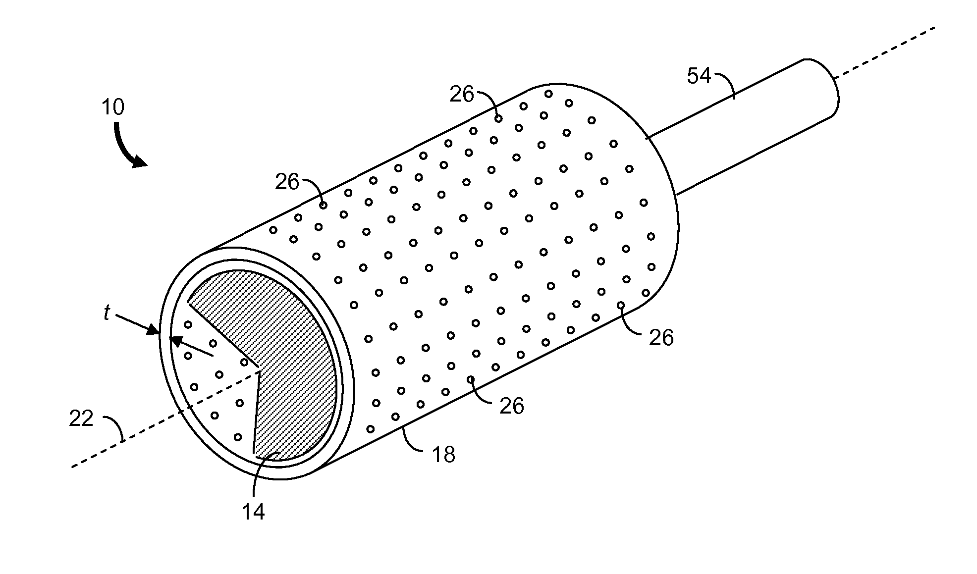
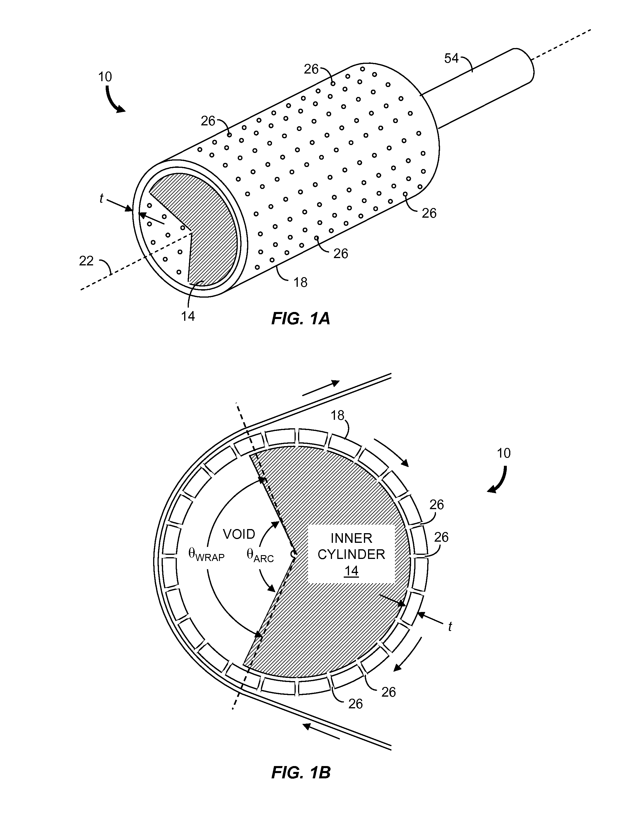
[0012]A common technique for cooling a web in a vacuum environment is to transport the web over a cooled roll or drum so that heat is transferred to the drum through contact. Cooling is adjusted by varying the temperature of the roll and the wrap angle of the web around the roll. The cooling rate is proportional to h*(T0−7) where h is the heat transfer coefficient, T0 is the temperature of the cooling roll and T is the temperature of the web. In vacuum, the interface between two materials generally does not have a high heat transfer coefficient h. More specifically, the natural roughness of a material at a microscopic level results in sharp points of contact; however, as heat conduction is proportional to the cross-sectional contact area, the transfer of heat across the interface is substantially limited. The introduction of a pliable material, such as an elastomer or a gas, between the materials results in a substantial improvement in cooling efficiency. The pliable material increa...


PUM

PropertyMeasurementUnit
Temperatureaaaaaaaaaa
Volumeaaaaaaaaaa
Heataaaaaaaaaa

Abstract

Described are an apparatus and a method for cooling a web. The apparatus includes an inner cylinder having a void therein and configured for coupling to a gas source. The apparatus also includes an outer cylinder having an inner surface, an outer surface to support a web and apertures between the inner and outer surfaces. The outer cylinder rotates about the inner cylinder so that gas provided to the void of the inner cylinder flows through the apertures that are adjacent to the void and passes to the outer surface of the outer cylinder to increase the heat transfer between the web and the outer cylinder. The volume of gas introduced into the vacuum deposition chamber during a process run is thereby limited. Advantageously, the apparatus enables higher deposition rates and increased productivity.

Description

FIELD OF THE INVENTION[0001]The invention relates generally to an apparatus and method for cooling a web during a deposition process. More particularly, the invention relates to an apparatus for cooling a web by injecting gas between the web and a rotating cooling cylinder.BACKGROUND OF THE INVENTION[0002]Roll to roll thin film vacuum deposition is often used to coat flexible materials such as plastics, metals and polyimide. In typical configurations a material or web substrate is unwound from a payout roll into a processing chamber. After a series of steps are performed, the coated web substrate is wound onto a take-up roll. Many of the deposition technologies that are commonly used require high vacuum conditions, for example, a pressure below 1 Torr. High vacuum deposition technologies include vacuum evaporation and sputtering, often referred to generically as physical vapor deposition. The deposition process induces a heat load on the web, resulting in an increase in temperature....

Claims


Application Information

Patent Timeline
IPC IPC(8): F28F7/00
CPCC23C14/562C23C14/50
Inventor SFERLAZZO, PIEROPOLNER, DONALD N.SIMONELLI, DARREN M.
Owner AVENTA TECH INC
Why Eureka
Try Eureka