
Mounting Stents On Stent Delivery Systems

a stent and stent technology, applied in the field of stent mounting on stent delivery system, can solve the problems of unfavorable stent crimping, unfavorable stent crimping, and insufficient stent crimping, so as to reduce the time required for crimping, reduce labor, and increase yield

Inactive Publication Date: 2012-01-12
ABBOTT CARDIOVASCULAR
View PDF10 Cites 60 Cited by
  • Summary
  • Abstract
  • Description
  • Claims
  • Application Information

AI Technical Summary

Benefits of technology

[0011]The invention provides an apparatus, system and process for crimping a stent to a balloon catheter. According to one aspect of the disclosure, a stent mounting system includes a crimper head and a pair of stations, located on opposite sides of the crimper head, for positioning first and second stent and catheter assemblies and aligning the first and second stents on their respective balloon catheters prior to crimping the stents to the balloons. The crimper head is adapted for receiving the stent and catheter assemblies from both stations to perform a crimping process at the same time. The system incorporates computer-controlled processes for reducing much of the labor typically required by an operator, e.g., a technician, when preparing a stent and catheter for crimping and monitoring the crimping process. Automated, computer-controlled processes replacing manual pre-crimping processes can increase yield, since there is less likelihood that a stent and catheter will be improperly located within the crimper head, which can result in uneven crimping over the length of a stent, or a stent not properly aligned with a balloon markers prior to crimping. By using automated, computer-controlled process the time required for crimping can be reduced, and production yields increased. Moreover, more operator time is made available, so that multiple crimping sequences can be monitored by the same operator.
[0012]These and other advantages of the invention are particularly worth noting when polymer stents are crimped. In contrast to a metal stent, a polymer stent must be crimped at a much slower rate due to the inherent limitations of the material compared at that of a metal. This slower process can produce significant bottlenecks during stent-catheter production. By automating manual crimping tasks, the overall time needed to crimp a polymer stent can be noticeably reduced. Polymer stents are more sensitive to fracture when crimping produces irregular bending or twisting of struts, since a polymer material suitable for a load-bearing stent, e.g., PLLA, is far more brittle than a metal. Inaccurate crimping within the crimper head, e.g., non-uniform applied forces through the crimper jaws when the stent and catheter are not properly located, or positioned within the crimper head, is therefore more likely to cause fracture in polymer stent struts. Accuracy and repeatability in the crimping process is therefore more critical to increased yield for a polymer stent than a metal stent. According to one aspect of the invention, there is a discovered need for more automation in a crimping process for polymer stents, whereas there is less need for automation when crimping metal stents. A crimping sequence for a polymer stent can be about five times longer than a metal stent. This 5-fold increase in crimping time, when multiplied out by the number of polymer stent-balloon assemblies crimped during a production run, poses unique challenges in planning and resource allocation, which is contrast to the time and resource allocation needed for crimping metal stents. A primary reason for the delay is the need to crimp the polymer material more slowly to reduce instances of crack creation or propagation, and to reduce recoil when the crimping jaws are removed from the stent surface.
[0013]Existing systems for crimping a stent to a balloon require an operator to both manually align stents between balloon markers, properly insert the stent and balloon assembly within a crimper head and then verify that the stent is being properly crimped in mid-process. The invention substantially overcomes many of the drawbacks of requiring an operator to perform these tasks by introducing automated processes for positioning and aligning a stent and catheter for crimping.
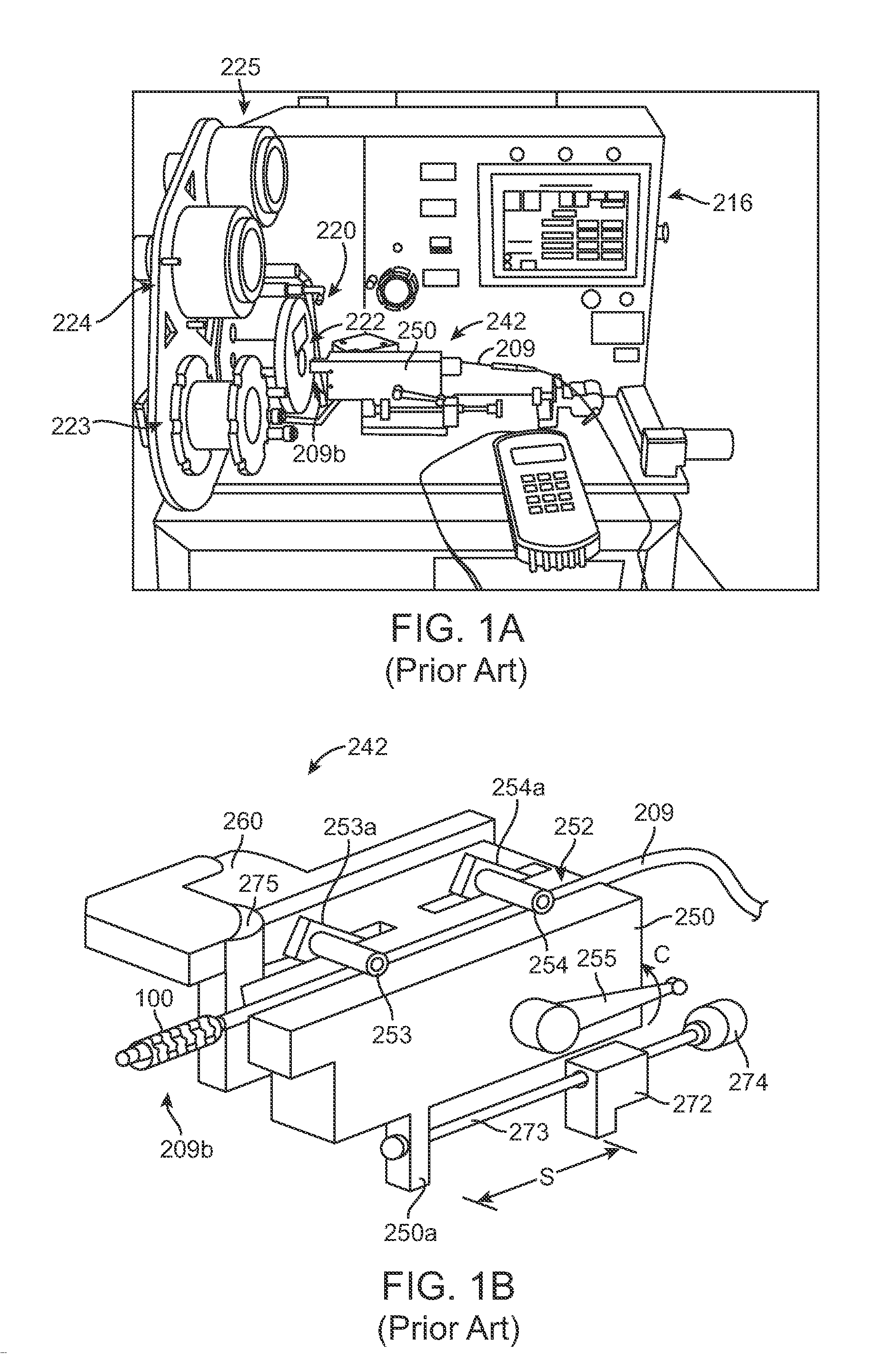
[0015]Manually positioning a catheter distal end at the entrance of the aperture and then manually advancing the stent and catheter within the crimper head. According to one aspect of the invention, a computer automatically advances the stent and catheter into the crimper head after an operator has verified, e.g., by a laser light identifying the proper location of the catheter's proximal balloon seal relative to a reference point, that the catheter has been properly placed within a carriage that advances the catheter and stent into the crimper head under computer control. A laser positioning system or a camera may be used to locate the proper placement of the catheter relative to the carriage, as well as to signal to a processor controlling the carriage motion forward into the crimper head that the stent-catheter as been positioned properly within the crimper head, once this signal is received, an actuator advances the stent-catheter assembly into the crimper head. The device illustrated in FIGS. 1A-1B, by contrast, utilizes a mechanical stop 275 to indicate to the operator that the stent-catheter assembly is located properly within the crimper head. However, it has been discovered that this manner of positioning the stent-catheter assembly within the crimper head can cause the stent to displace relative to the balloon, thereby throwing the stent out of alignment. The invention recognizes that a mechanical stop, even when found suitable for positioning a metal stent within a crimper head, introduces problems for polymer stents, particularly when the polymer stent has a much larger diameter than the balloon. As a solution to this problem, a servo mechanism is used to advance the stent-catheter assembly into the crimper head at a rate which reduces the chance that the stent will move relative to the balloon.

Problems solved by technology

Automated, computer-controlled processes replacing manual pre-crimping processes can increase yield, since there is less likelihood that a stent and catheter will be improperly located within the crimper head, which can result in uneven crimping over the length of a stent, or a stent not properly aligned with a balloon markers prior to crimping.
In contrast to a metal stent, a polymer stent must be crimped at a much slower rate due to the inherent limitations of the material compared at that of a metal.
This slower process can produce significant bottlenecks during stent-catheter production.
Inaccurate crimping within the crimper head, e.g., non-uniform applied forces through the crimper jaws when the stent and catheter are not properly located, or positioned within the crimper head, is therefore more likely to cause fracture in polymer stent struts.
This 5-fold increase in crimping time, when multiplied out by the number of polymer stent-balloon assemblies crimped during a production run, poses unique challenges in planning and resource allocation, which is contrast to the time and resource allocation needed for crimping metal stents.

Method used


Image

  • Mounting Stents On Stent Delivery Systems
  • Mounting Stents On Stent Delivery Systems
  • Mounting Stents On Stent Delivery Systems

Examples


Embodiment Construction

[0042]Throughout this disclosure, the balloon expandable implant will be called a “stent”, whether the description is referring to an implant made in whole or part of a metal material or a polymeric material such as PLLA. In some instances, the term “scaffold” may be used, which is specifically referring to a biodegradable, polymer implant.

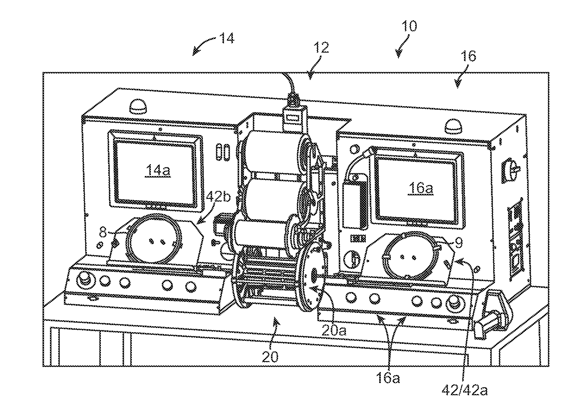
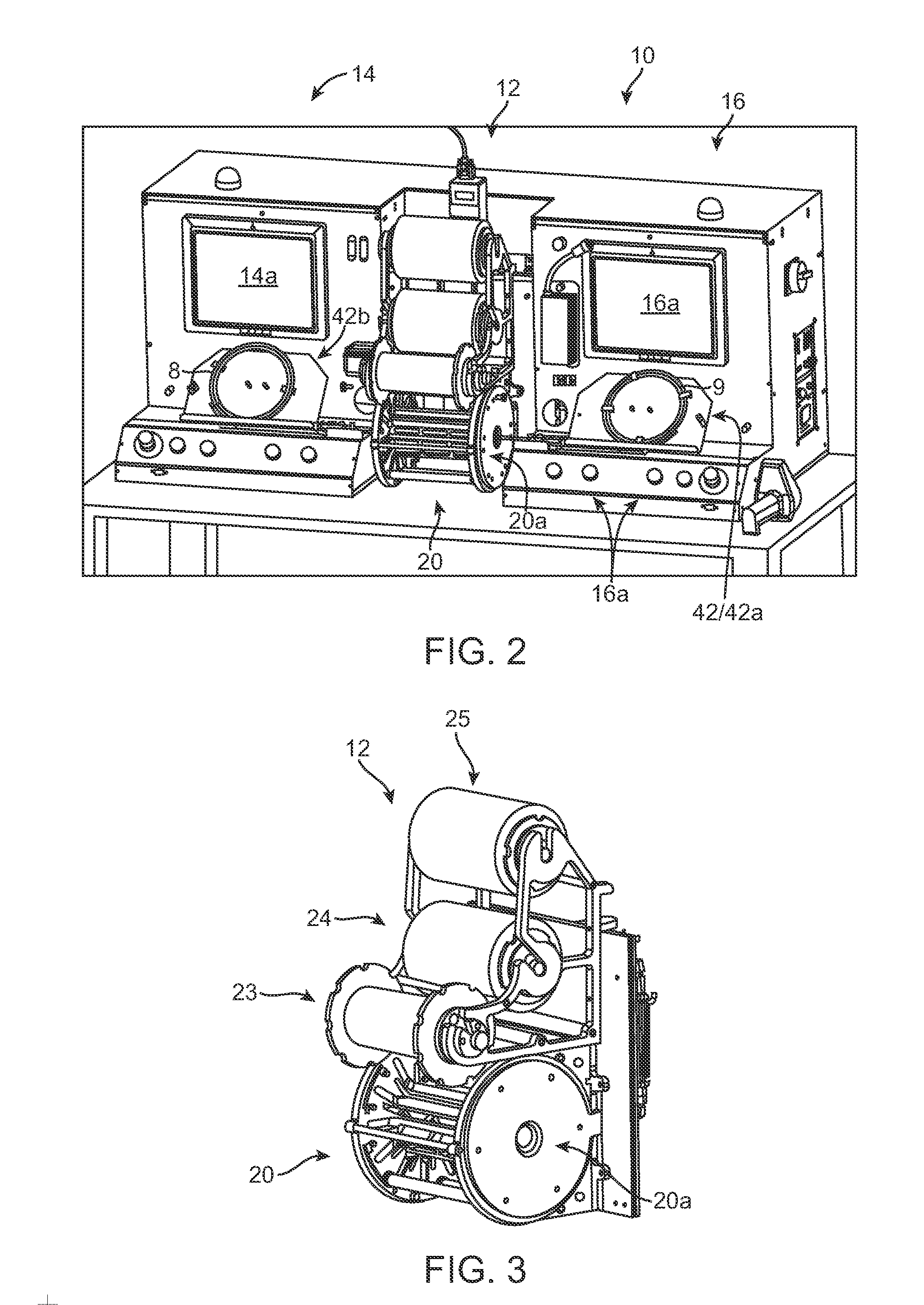
[0043]FIG. 2 illustrates a stent mounting system 10 according to one aspect of the disclosure. The stent mounting system 10 is configured for positioning a stent on a delivery balloon, then crimping the stent to the balloon in an automated fashion. The system 10 is preferably constructed so that two stents may be simultaneously loaded onto separate balloon catheters, then each placed within a crimper head by a computer-controlled positioning and alignment system. Both stents are then crimped to their respective balloon using the same crimper head. As such, two stents may be simultaneously crimped to catheters during a single crimping sequence. The...


PUM

PropertyMeasurementUnit
Temperatureaaaaaaaaaa
Forceaaaaaaaaaa
Diameteraaaaaaaaaa

Abstract

A system for mounting a stent on a balloon catheter includes two positioning and alignment stations, which are used to prepare a stent and catheter for crimping using the same crimping head. The system is configured for automated assembly of the stent and catheter prior to crimping. A catheter and stent are placed on a computer-controlled carriage that delivers the stent and catheter to the crimper head. Before placing the stent and catheter into the crimper head, an automated alignment system locates the stent between balloon markers.

Description

BACKGROUND OF THE INVENTION[0001]1. Field of the Invention[0002]The present invention relates to drug-eluting medical devices; more particularly, this invention relates to systems, apparatus and methods for mounting to a delivery balloon a balloon-expandable stent, such as a polymeric stent.[0003]2. Background of the Invention[0004]FIGS. 1A and 1B depict perspective views of a prior art crimping station used to crimp a balloon expandable stent to a deployment balloon of a balloon catheter. The crimping station includes a crimper head 220, an interactive screen 216 for programming a crimping sequence, e.g., diameter reduction, dwell times between successive crimps, temperature control of the crimper jaws, etc. A carriage 242 aligns a catheter 209 with the opening 222 to the crimper head 220 and advances the distal end 209b of the catheter, where a stent 100 and the balloon are located, into the crimper head 220. The crimper head 220 includes three rollers 223, 224 and 225, which plac...

Claims


Application Information

Patent Timeline
IPC IPC(8): A61F2/84
CPCA61F2002/9522A61F2/958Y10T29/53978Y10T29/53022Y10T29/49902Y10T29/53917Y10T29/53987Y10T29/53065A61F2002/9583A61F2/9522A61F2/9524
Inventor VAN SCIVER, JASON
Owner ABBOTT CARDIOVASCULAR
Learn More