Nonreciprocal circuit element

a non-reciprocal, circuit element technology, applied in the direction of basic electric elements, waveguide devices, electrical equipment, etc., can solve the problems of increasing product size and cost, difficult to stably mass-produce non-reciprocal circuit elements having the desired characteristic, etc., to achieve the effect of improving isolation characteristics, increasing reliability, and not increasing insertion loss

Active Publication Date: 2012-01-26
MURATA MFG CO LTD
View PDF0 Cites 30 Cited by
  • Summary
  • Abstract
  • Description
  • Claims
  • Application Information

AI Technical Summary

Benefits of technology

[0011]In the nonreciprocal circuit element, when a high-frequency current is input into the output port, the impedance characteristics of the first parallel resonant circuit and the second parallel resonant circuit achieve matching in a wide frequency band. As a result, an isolation characteristic is improved. On the other hand, when a high-frequency current flows from the input port to the output port, a large high-frequency current flows through the second center electrode and a high-frequency current hardly flows through the two parallel resonant circuits. Accordingly, an insertion loss resulting from the addition of the first parallel resonant circuit can be ignored, and an insertion loss is not increased.
[0012]In particular, the inductor included in the second parallel resonant circuit may have a small inductance value, and can be therefore applied to a nonreciprocal circuit element

Problems solved by technology

However, this leads to increases in a product size and a cost.
This leads to unreliability.
However, in a capacitor having a small capacitance value, an effective capacitance value is significantly changed because of the

Method used


Image

  • Nonreciprocal circuit element
  • Nonreciprocal circuit element
  • Nonreciprocal circuit element

Examples


first preferred embodiment

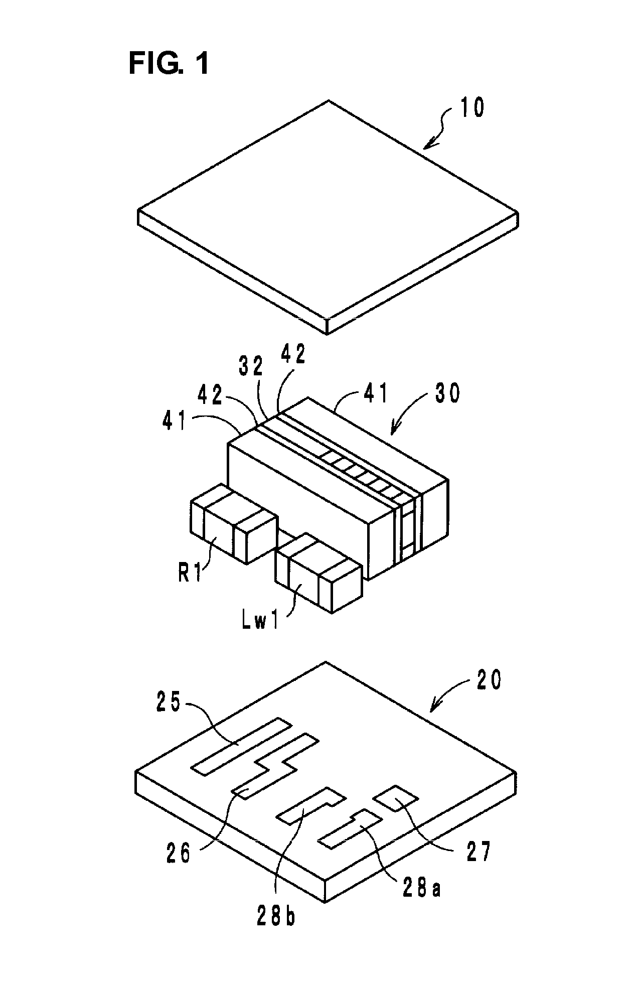
[0025]A nonreciprocal circuit element (two-port isolator) according to the first preferred embodiment preferably is a lumped-constant isolator, and includes a circuit board 20, a ferrite-magnet assembly 30 including a ferrite 32 and a pair of permanent magnets 41, a substantially planar yoke 10, a chip resistor R1, and a chip inductor Lw1 as illustrated in FIG. 1.

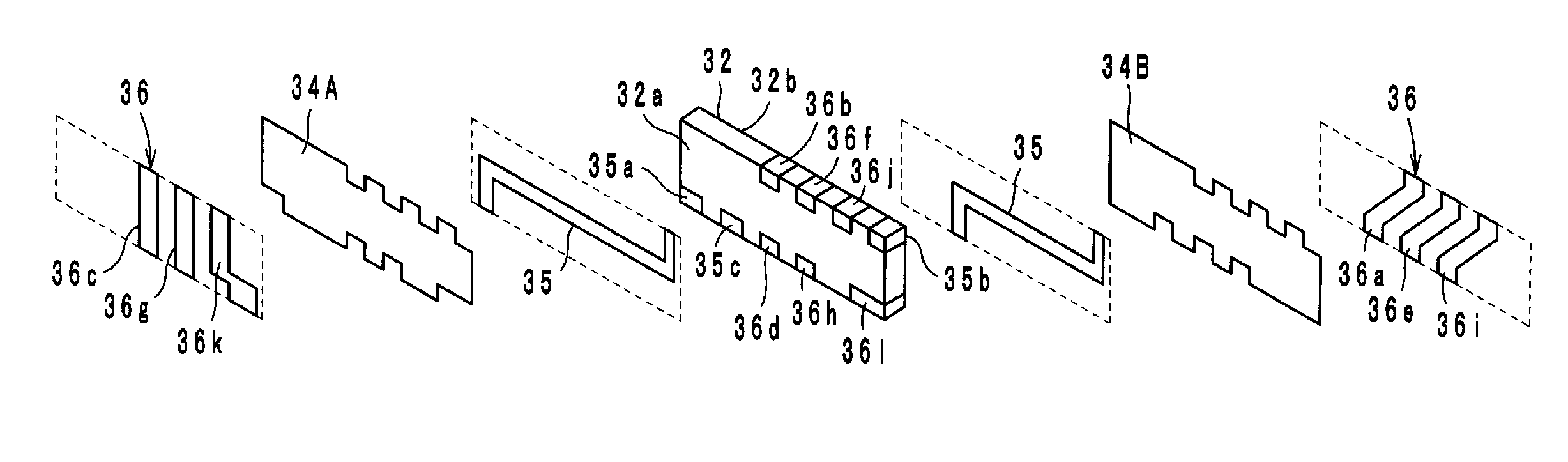
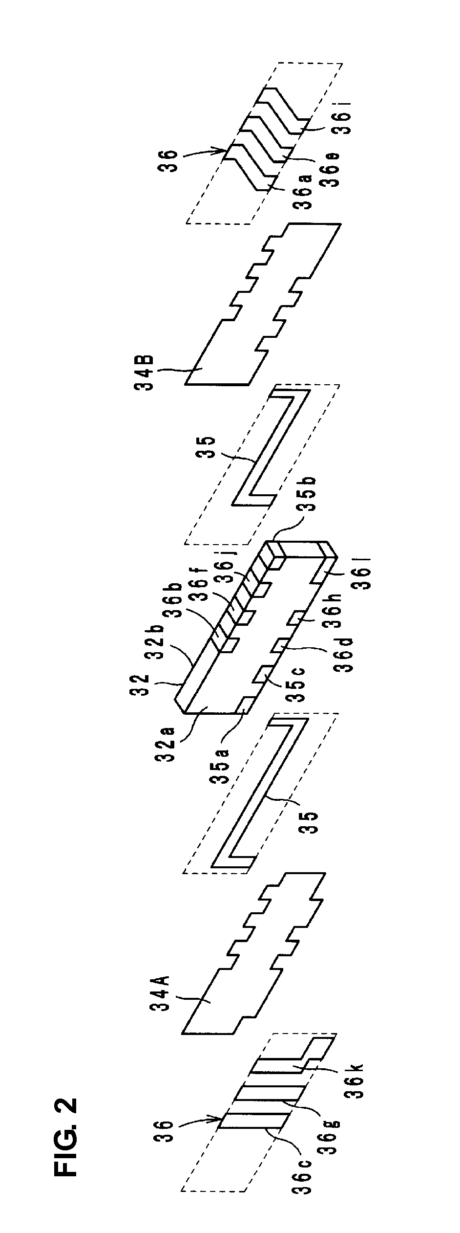
[0026]As illustrated in FIG. 2, in the ferrite 32, a first center electrode 35 and a second center electrode 36 are electrically insulated from each other by an insulating material 34A on a first main surface 32a, and the first center electrode 35 and the second center electrode 36 are electrically insulated from each other by an insulating material 34B on a second main surface 32b. The ferrite 32 preferably has a substantially rectangular parallelepiped shape, for example, including the first main surface 32a and the second main surface 32b that face each other and are parallel or substantially to each other.

[0027]The perm...

second preferred embodiment

[0054]As illustrated in an equivalent circuit diagram in FIG. 6, a nonreciprocal circuit element (two-port isolator) according to the second preferred embodiment is preferably substantially the same as that according to the first preferred embodiment except that an inductor Lw2 is preferably used as an element to connect the LC parallel resonant circuits 51 and 52. Accordingly, in the second preferred embodiment, operational effects and advantages similar to that obtained in the first preferred embodiment can be obtained.

[0055]An insertion loss characteristic and an isolation characteristic of a two-port isolator according to the second preferred embodiment will be described with reference to FIGS. 7 and 8. An insertion loss characteristic and an isolation characteristic are based on pieces of data of measurement performed on a two-port isolator having the following specifications.[0056]Inductor L1: approximately 2.50 nH[0057]Inductor L2: approximately 6.60 nH[0058]Capacitor C1: app...

third preferred embodiment

[0068]As illustrated in an equivalent circuit diagram in FIG. 9, a nonreciprocal circuit element (two-port isolator) according to the third preferred embodiment is preferably substantially the same as that according to the second preferred embodiment except that two capacitors Cw11 and Cw12 are used instead of the capacitor Cw1 in the LC parallel resonant circuit 51. Accordingly, in the third preferred embodiment, operational effects and advantages described in the first preferred embodiment can be obtained.

[0069]There is a certain variation in a capacitance value of a capacitor. The variation in a capacitance value in a case where two capacitors are used is smaller than that in a case where a single capacitor is used. The reason for this is that, when a capacitance value standard deviation in a case where n capacitors are used is calculated under the assumption that the distribution of the variation in a capacitance value of a single capacitor is a normal distribution and a capacit...


PUM


Abstract

A nonreciprocal circuit element includes first and second center electrodes. On a ferrite to which a direct-current magnetic field is applied from a permanent magnet, the first and second center electrodes are insulated and intersect. First and second ends of the first center electrode are connected to an input port and an output port, respectively. First and second ends of the second center electrode are connected to the output port and a ground port, respectively. A first matching capacitor and a resistor are connected between the input port and the output port. A second matching capacitor is connected between the output port and the ground port. A parallel resonant circuit is connected in parallel to the resistor. A coupling element is connected between the parallel resonant circuit and another parallel resonant circuit including the first center electrode and the first matching capacitor so as to the parallel resonant circuits.

Description

BACKGROUND OF THE INVENTION[0001]1. Field of the Invention[0002]The present invention relates to nonreciprocal circuit elements, and, more particularly, to a nonreciprocal circuit element such as an isolator or a circulator used in a microwave band.[0003]2. Description of the Related Art[0004]A nonreciprocal circuit element such as an isolator or a circulator has a characteristic of transmitting a signal in only a predetermined direction and transmitting no signal in the opposite direction, and is used in, for example, a transmission circuit of a mobile communication device such as a car phone or a mobile phone.[0005]WO Publication No. 2009 / 028112 discloses, as this kind of nonreciprocal circuit element, a two-port isolator in which a first center electrode and a second center electrode intersect and are insulated from each other on a ferrite surface and an LC series resonant circuit including a capacitor and an inductor is connected in parallel to the first center electrode and is ...

Claims


Application Information

Patent Timeline
IPC IPC(8): H01P1/36
CPCH01P1/387H01P1/36
Inventor HINO, SEIGOYAMADA, YOSHIKI
Owner MURATA MFG CO LTD
Why Eureka
Try Eureka