Quartz Boat Method and Apparatus for Thin Film Thermal Treatment

a technology of thermal treatment and quartz boat, which is applied in the direction of lighting and heating apparatus, charge supports, furnaces, etc., can solve the problems of high cost of crystalline materials, low energy conversion efficiency of devices made from such crystalline materials, and many limitations, so as to increase the number of planar substrates loaded in the quartz boat fixture, the effect of easily ramping the furnace temperature down

Inactive Publication Date: 2012-01-26
CM MFG
View PDF1 Cites 47 Cited by
  • Summary
  • Abstract
  • Description
  • Claims
  • Application Information

AI Technical Summary

Benefits of technology

[0013]The invention provide an apparatus for holding a plurality of planar substrates overlaid with photovoltaic precursor layers in a furnace tube. The furnace tube has heaters to supply heat energy in a controlled manner. The furnace can be filled with desired gaseous species including selenium and/or sulfur for a reactive thermal treatment of the precursor layer for manufacture of photovoltaic cells. In particular, the apparatus utilizes a quartz boat fixture having a rack fixture configured with a plurality of grooves for supporting large planar (rectangular or square in most cases) glass substrates. Some embodiments of the invention provide loading configurations of a plurality of planar substrates in the boat fixture by aligning them vertically, arranging the plurality of grooves with a proper size for each one, and disposing them with an optimum spacing between each other and in periodic groups, and others. In some embodiments, the loading configurations of the substrates in the quartz boat fixture allow an effective convection flow in between the planar substrates to transfer heat energy from hotter regions to cooler regions of the each substrate during the reactive thermal treatment process.
[0014]In a specific embodiment, the temperature across each substrate is maintained substantially uniform or at least the temperature difference is controlled to be smaller than a set value. In another specific embodiment, an alternative loading configuration includes two substrates being

Problems solved by technology

Although solar energy is environmentally clean and has been successful to a point, many limitations remain before it becomes widely used throughout the world.
However, crystalline materials are often costly and difficult to make on a large scale.
Additionally, devices made from such crystalline materials often have low energy conversion efficiencies.
Similar limitations exist with the use of thin film technology in making solar cells.
That is, efficiencies are often poor.
Additionally, film reliability is often poor and cannot be used for extensive periods of time in conventional environmental applications.
Often, thin films are d

Method used


Image

  • Quartz Boat Method and Apparatus for Thin Film Thermal Treatment
  • Quartz Boat Method and Apparatus for Thin Film Thermal Treatment
  • Quartz Boat Method and Apparatus for Thin Film Thermal Treatment

Examples


Embodiment Construction

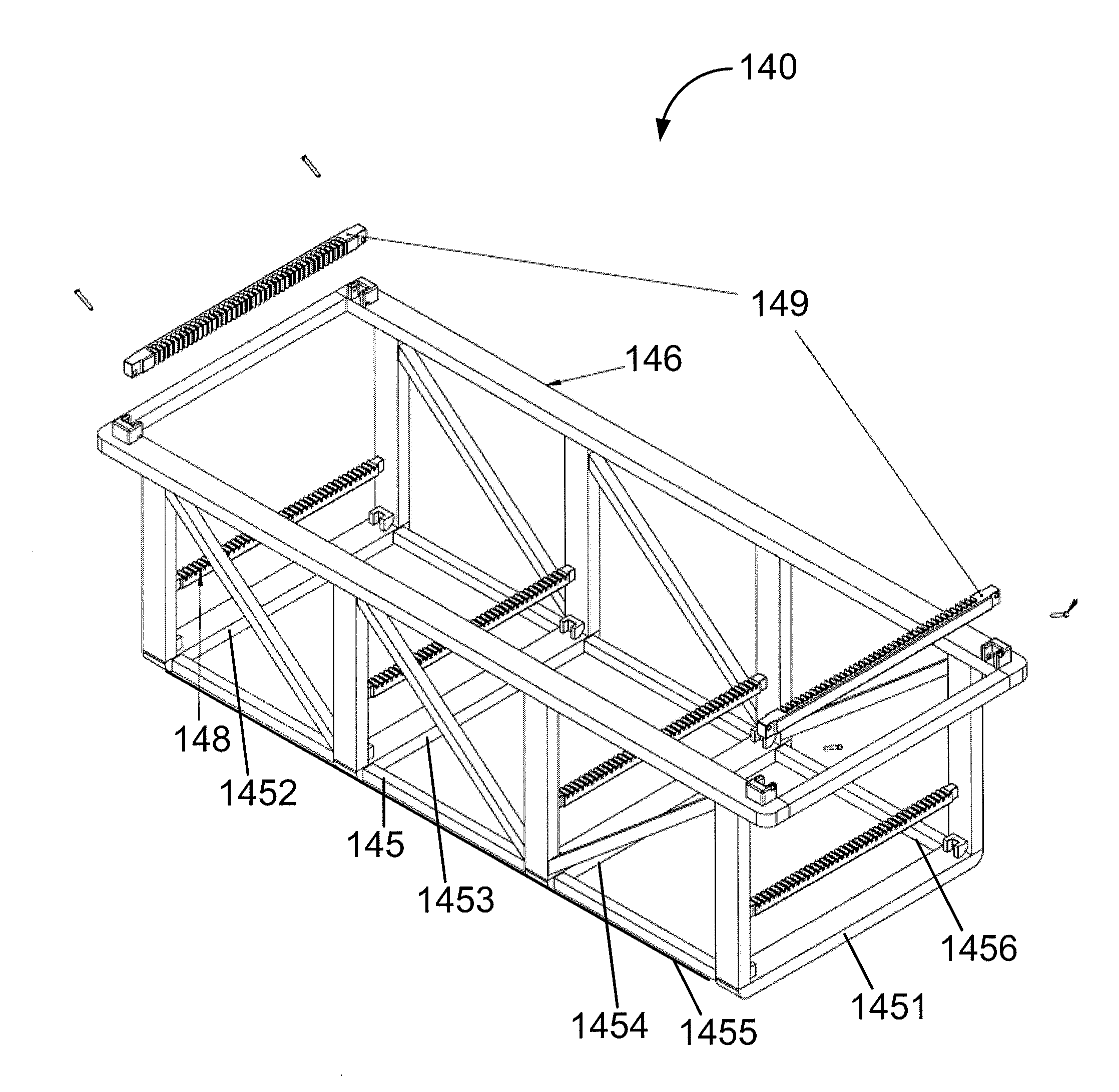
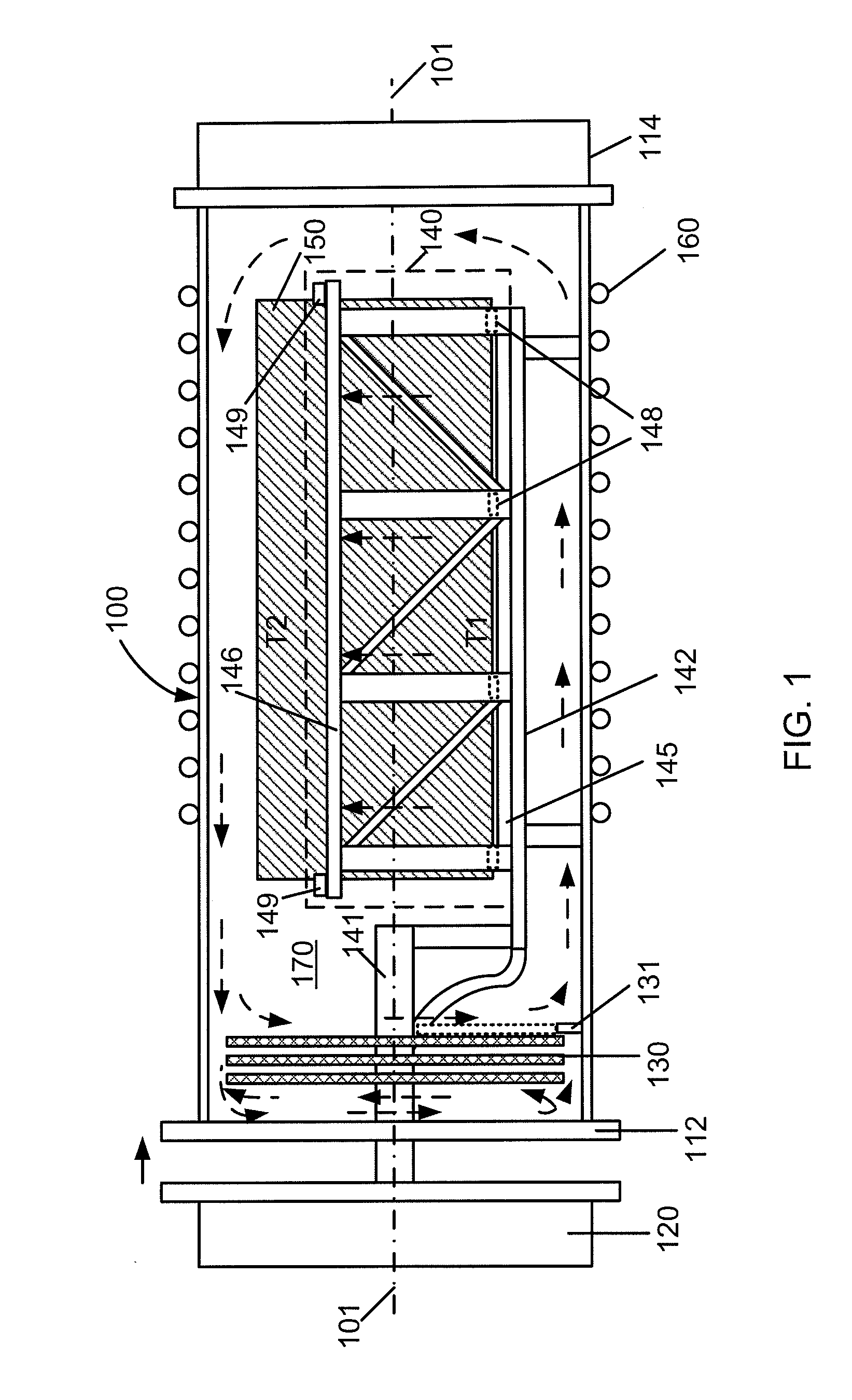
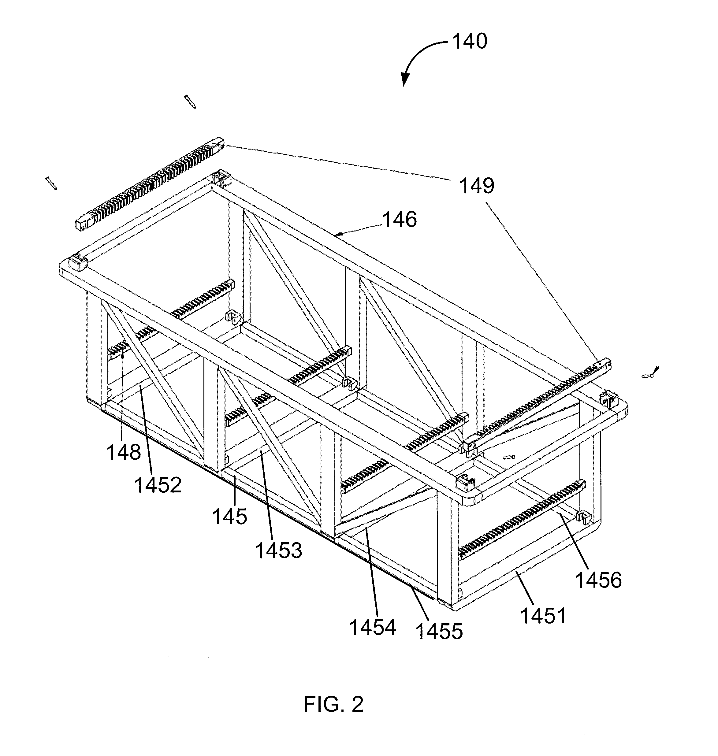
[0022]FIG. 1 is a side view along an axis of a furnace tube including a quartz boat fixture with loaded planar substrates for manufacture of photovoltaic cells according to an embodiment of the present invention. As shown, the furnace tube 100 is characterized by a length of tubular shaped container or chamber enclosing a volume of space. In an embodiment, the furnace tube 100 has a first end 112 that is configured to be engaged, covered, and sealed by a cover member (or a door) 120 and a second end 114 on the opposite side. The inner wall of the furnace tube 100 is a smooth surface for facilitating internal gas convection during thermal process. In another embodiment, the furnace tube 100 is set up in an orientation with its tube axis 101 along horizontal (or floor) direction. The second end 114 can be also opened and usually is thermally insulated. A gas supply device and / or a gas monitor (not shown) can be coupled to the furnace tube 100 for providing a controllable gaseous envir...


PUM


Abstract

A method of supporting a plurality of planar substrates in a tube shaped furnace for conducting a thermal treatment process is disclosed. The method uses a boat fixture having a base frame including two length portions and a first width portion, a second width portion, and one or more middle members connected between the two length portions. Additionally, the method includes mounting a removable first grooved rod respectively on the first width portion, the second width portion, and each of the one or more middle members, each first grooved rod having a first plurality of grooves characterized by a first spatial configuration. The method further includes inserting one or two substrates of a plurality of planar substrates into each groove in the boat fixture separated by a distance.

Description

CROSS-REFERENCE TO RELATED APPLICATION[0001]This application claims priority to U.S. Provisional Application No. 61 / 367,211, filed Jul. 23, 2010, commonly assigned, and hereby incorporated by reference in its entirety herein for all purpose.BACKGROUND OF THE INVENTION[0002]The present invention relates generally to photovoltaic materials and manufacturing method. More particularly, the present invention provides a method and apparatus for thin film thermal treatment. Embodiments of the invention include a method and apparatus for holding a plurality of extra large substrates for achieving substantially uniform substrate temperature during a thermal process to form a photovoltaic absorber material, but it would be recognized that the invention may be applied for other thin-film treatment applications.[0003]From the beginning of time, mankind has been challenged to find ways of harnessing energy. Energy comes in forms such as petrochemical, hydroelectric, nuclear, wind, biomass, solar...

Claims


Application Information

Patent Timeline
IPC IPC(8): H01L31/18B25B11/00
CPCH01L21/67109H01L21/67313H01L21/67316H01L31/18H01L21/6734
Inventor ALEXANDER, PAULSCHMITZBERGER, JURGTANDON, ASHISHWIETING, ROBERT D.
Owner CM MFG
Why Eureka
Try Eureka