Thermoformed or Molded Partition

a technology of partitions and molded parts, applied in the field of partitions, can solve the problems of easy scratching of finish, easy rusting, corrosion and vandalism, and easy damage to metal, and achieve the effects of easy cleaning, strong bonding, and anti-graffiti protection

Inactive Publication Date: 2012-02-02
SCRANTON PROD
View PDF3 Cites 3 Cited by
  • Summary
  • Abstract
  • Description
  • Claims
  • Application Information

AI Technical Summary

Benefits of technology

[0012]We provide a partition that is preferably thermoformed from two sheets of plastic, preferably high density polyethylene. One preferred fabrication method is twin sheet thermoforming. The two sheets are heated and placed between a pair of thermoforming molds or dies. The molds are configured such that the partition formed from the two sheets will have regions where the sheets are spaced apart from one another and regions where the sheets abut one another such that the abutting surfaces are bonded together. These bonded regions impart strength to the partition and make the panel cosmetically pleasing. The resulting partition has all of the advantages of prior art partitions made from plastic. It is sanitary, easy to clean and relatively graffiti proof. However, those partitions weigh considerably less than panels of the same size which are known in the prior art. We may also make these partitions using injection molding or vacuum molding techniques.
[0013]The process of forming or molding plastic partitions reduces the weight of the panels by decreasing the wall thickness and / or creating hollows. With a reduction in weight a single installer can now handle the panels during installation. For example, a solid plastic partition weighs two to four times that of our partition.
[0014]The forming or molding process decreases fabrication time. An example of a typical panel fabrication process for our partition is heat two sheets of resin, form them into a partition, cool the partition and then trim it. These steps can all be fully automated. An added benefit is that part quality is assured with dedicated tools and defined processes.
[0015]Partitions made in accordance with its present invention will be less expensive than prior art plastic partitions because less resin is used and labor costs will be low using a fully automated manufacturing process.
[0016]Besides the obvious cost decrease, a decrease in the volume of resin also benefits the environment. The formed or molded components can be fabricated from a recyclable resin. However, the less resin used the less the burden to recycle. With the thin wall or hollow nature of these formed components the resin reduction is two to four times that of their solid plastic counterparts.

Problems solved by technology

However, it is very susceptible to rusting, corrosion and vandalism.
In addition, the finish can be scratched easily and the metal can be dented.
But these panels have the same disadvantages.
This provides some advantages, but also increases the cost of the panel construction.
Like baked enamel panel constructions, stainless steel panel constructions are susceptible to denting.
Moreover, there are several commercial cleaning solutions that will cause the stainless steel to corrode.
Moisture can enter these panels and degrade the cardboard as well as cause corrosion of the metal.
This moisture also creates an unsanitary condition.
Moisture is trapped in the interior of the panel and that interior cannot be accessed for cleaning.
Patterns may be embossed upon plastic panels that make scratches less noticeable and make it difficult to mar or mark the panels with graffiti.
Although the surface is harder-than the baked enamel, once it is scratched there is no way to fix it short of replacing the entire panel.
Any damage to the panel requires its complete replacement.
The size of these panels impose practical limits on the methods which can be used to form the panels; while compression molding is acceptable, extrusion or pultrusion are more costly and therefore may be unacceptable.
This in turn limits the types of material which can be used.
Many of the larger plastic panels can be quite heavy such that at least two people are needed to install these partitions.

Method used


Image

  • Thermoformed or Molded Partition
  • Thermoformed or Molded Partition
  • Thermoformed or Molded Partition

Examples


Embodiment Construction

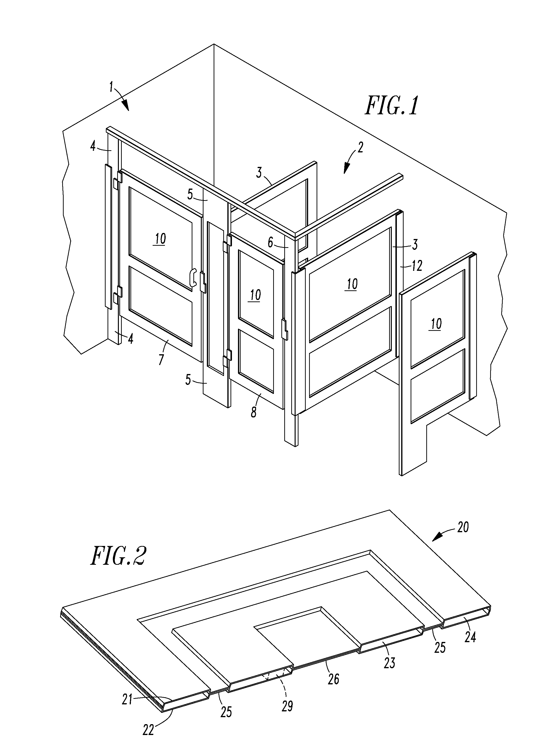
[0022]Bathrooms in public buildings and other locations often have several toilets and may have several urinals each mounted against a wall of the building. A partition is provided on either side of each toilet. These partitions are attached to the wall at one end and to a post at the opposite end. A door is hung from and between the posts. The door is usually made from the same type of fabrication process as is used for the partitions. Urinals are often separated by a partition attached to the wall between adjacent urinals. Similar partitions may be used in showers, dressing rooms and even desk cubicles.

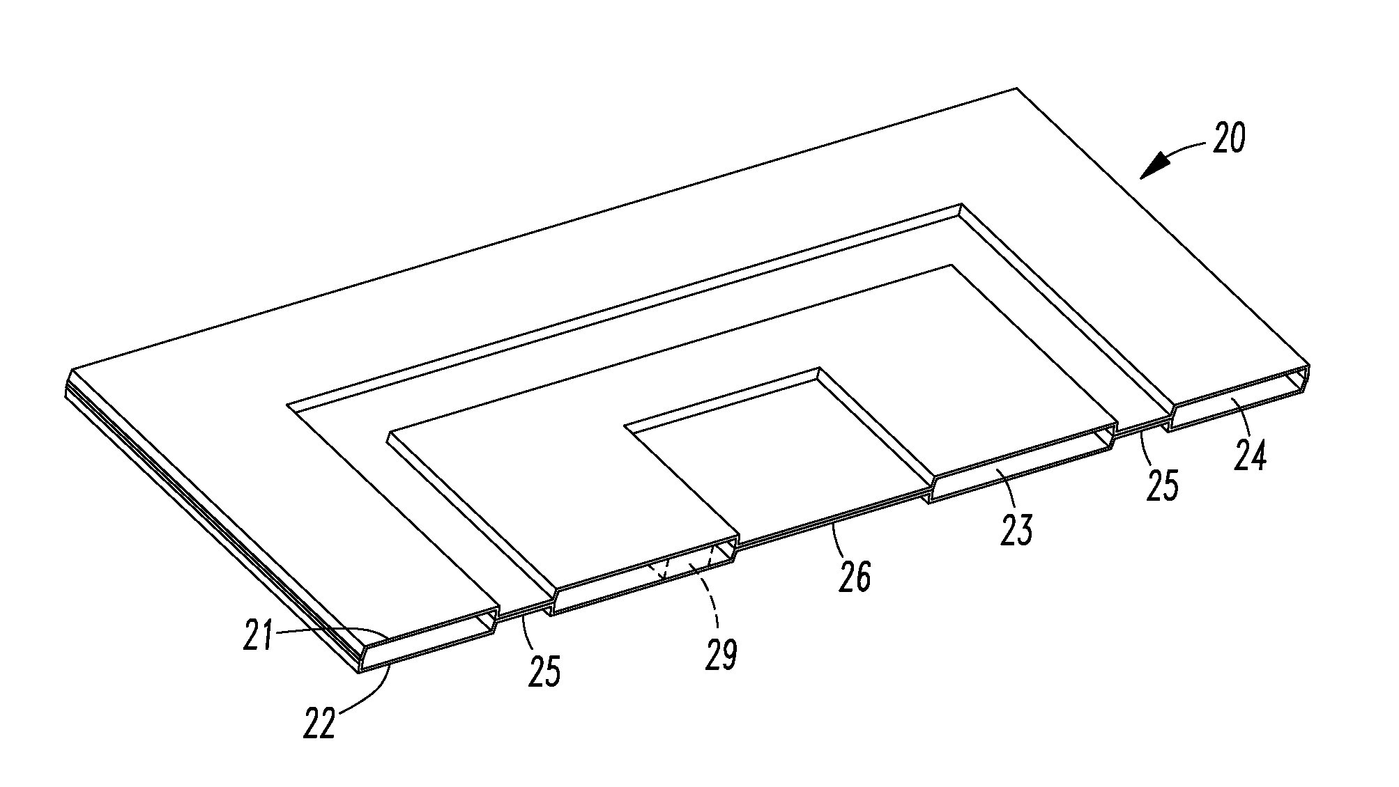
[0023]FIG. 1 illustrates a portion of a bathroom having two toilets and two urinals. Partitions and doors are provided to define two stalls 1 and 2. Partitions 3 extend from the wall on either side of the second stall. The first stall 1 is defined by a wall of the building and the partition 3 which is parallel to that wall. Posts 4, 5 and 6 are provided to carry the doors 7 and 8 fo...


PUM

PropertyMeasurementUnit
weightaaaaaaaaaa
perimeteraaaaaaaaaa
densityaaaaaaaaaa

Abstract

A partition panel is made of two overlaying sheets of high density polyethylene or other plastic material which have been bonded together around a perimeter and at selected regions such that the partition panel contains bonded regions where the two sheets are bonded together and hollow regions where the two sheets are spaced apart from one another. The partition panel is preferably made by thermoforming.

Description

FIELD OF INVENTION[0001]The invention relates to partitions that are used to define and separate areas such as bathroom stalls and provide privacy.BACKGROUND OF THE INVENTION[0002]Five major types of panel constructions are currently in wide use for bathroom partitions. These are typically categorized by the material used for the door and side panels and include metal with a baked enamel finish, stainless steel, plastic laminate, solid phenolic and solid plastic.[0003]The baked enamel metal panel constructions consist of 20 to 22 gauge galvanized steel wall panels and door panels with a honeycomb core. The core is glued to the metal skins and the edges are covered with a locking cap molding. The finish of these panels is baked on enamel. The advantage of this type of panel construction is its low cost. However, it is very susceptible to rusting, corrosion and vandalism. In addition, the finish can be scratched easily and the metal can be dented. Painted or powder coated panels have ...

Claims


Application Information

Patent Timeline
Patent Type & Authority Applications(United States)
IPC IPC(8): B32B3/00B29C37/02B29C69/00
CPCB29C51/105B29C2791/006B32B3/08Y10T428/24661B32B27/08B32B27/32B32B3/28B32B2270/00B32B2307/732B32B2419/00B32B2607/00
Inventor FARNSWORTH, HILARYDAIUTE, DAVIDMITCHELL, STEW
Owner SCRANTON PROD
Why Eureka
Try Eureka