Check patentability & draft patents in minutes with Patsnap Eureka AI!

Method and system for parallel computation of linear sequential circuits

a sequential circuit and parallel computation technology, applied in the field of linear sequential circuits, can solve the problems of insufficient high-speed wireless communication system, limited computation speedup (usually 8 or less), and traditional processor/dsp associated with the wireless communication system is not equipped to deal with linear sequential circuits, etc., to achieve flexible and inexpensive solutions, improve computational speed, and improve computational speed

Active Publication Date: 2012-02-02
BEIJING XIAOMI MOBILE SOFTWARE CO LTD
View PDF2 Cites 9 Cited by
  • Summary
  • Abstract
  • Description
  • Claims
  • Application Information

AI Technical Summary

Benefits of technology

[0008]It is further aspect of the disclosed embodiment to provide for an improved system and method for parallel computation of an LSC based on a state transition matrix in order to improve computational speed.
[0009]The aforementioned aspects and other objectives and advantages can now be achieved as described herein. A method and system for parallel computation of a linear sequential circuit (LSC) based on a state transition matrix is disclosed herein. A multistep state transition matrix and a multistep output generation matrix can be pre-computed and stored in association with the linear sequential circuit (e.g., a linear feedback shift register, a linear feed forward shift register). The multiple state transitions and the multiple output bits can be computed by multiplying the current input-state vector with a multistep next state transition matrix and a multistep output generation matrix, respectively. Multiple state transitions and multiple output bits can be generated in parallel in a single clock cycle based on the pre-computed state transition matrix and the output generation matrix utilizing a dot product (e.g., Galois field dot product) in order to improve computational speed. Such a simple augmentation provides a flexible and inexpensive solution for high speedup linear sequential circuit computation with respect to a processor (e.g., traditional DSP).
[0010]The dot product can be computed utilizing a GF(2) binary finite field dot product accelerator. The multistep (k-step) state transition matrix and the multistep (k-step) output generation matrix can be represented as a control bit array in the linear sequential circuit. The multistep state transition matrix and the multistep output generation matrix can be loaded to a register of the processor. The combinational logic in a linear sequential circuit, can be efficiently implemented in a processor for augmenting a processor's instruction set for supporting a communication system. The next state transition matrix and the output generation matrix can be computed offline and preloaded into the matrix storage elements or control bit array in order to utilize the proposed instruction / intrinsic for a linear sequential circuit function. The instruction then takes the state-input vector as the input of the instruction and generates the next state and the output bits as the output of the instruction. The newly computed next state and the next input bits can be employed as the new state-input vector for computing the output and the instruction can then be put in a loop to generate as many output bits with a high computational speed.

Problems solved by technology

Such prior art sequential circuits generate one bit of output in a single clock cycle, which is not adequate for a high-speed wireless communication system.
Additionally, a traditional processor / DSP associated with the wireless communication system is not equipped to deal with the linear sequential circuit and each bit in the linear sequential circuit needs to be shifted, masked and manipulated in order to perform the linear sequential circuit computations.
Furthermore, such linear sequential circuit requires a number of cycles to implement a single step transition.
Such an approach, however, provides limited computation speedup (usually 8 or less) due to the exponential cost increase required by the larger lookup table to support higher speedup.

Method used


Image

  • Method and system for parallel computation of linear sequential circuits
  • Method and system for parallel computation of linear sequential circuits
  • Method and system for parallel computation of linear sequential circuits

Examples


Embodiment Construction

[0017]The particular values and configurations discussed in these non-limiting examples can be varied and are cited merely to illustrate at least one embodiment and are not intended to limit the scope thereof.

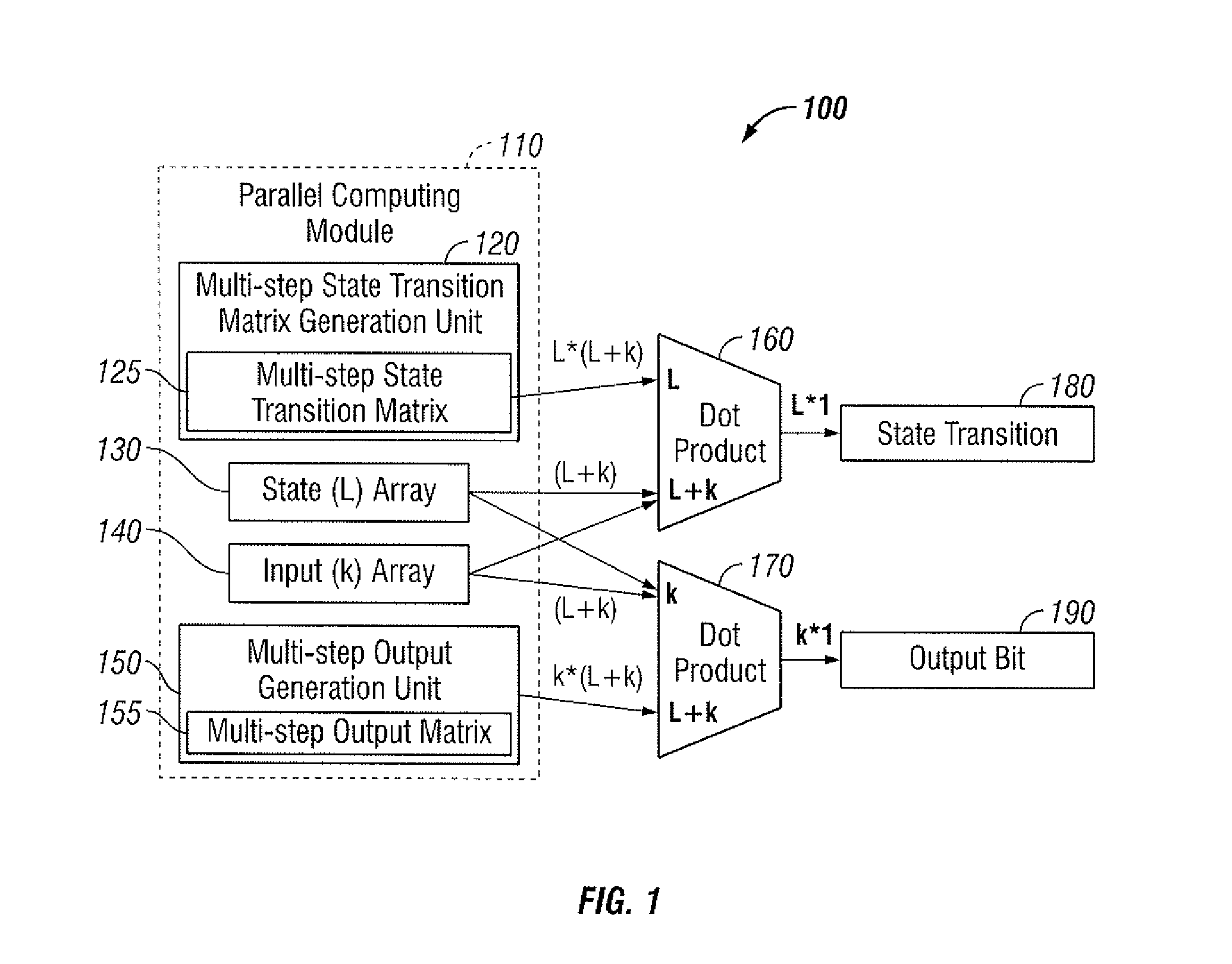
[0018]FIG. 1 illustrates a block diagram representing parallel computation in a linear sequential circuit 100, in accordance with the disclosed embodiments. The linear sequential circuit 100 depicted in FIG. 1 can be configured to include a parallel computing module 110 for improving the computational speed of the linear sequential circuit 100. Note that the linear sequential circuit 100 can be, such as, for example, a linear feedback shift register (LFSR), a linear feed forward shift register (LFFSR), or a combination of both, depending upon design considerations. Note that the LFSR is just a subset of LSC and there are LSC circuits that are neither LFSR nor LFFSR.

[0019]The parallel computing module 110 can be configured to include a multistep state transition matrix generatio...


PUM


Abstract

A method and system for parallel computation of a linear sequential circuit (LSC) based on a state transition matrix is disclosed herein. A multistep state transition matrix and a multistep output generation matrix can be pre-computed and stored in association with the linear sequential circuit. The multiple state transitions and the multiple output bits can be computed by multiplying the current input-state vector with a multistep next state transition matrix and a multistep output generation matrix, respectively. Multiple state transitions and multiple output bits can be generated in parallel in a single clock cycle based on the pre-computed state transition matrix and the output generation matrix utilizing a dot product in order to improve computational speed. Such a simple augmentation provides a flexible and inexpensive solution for high speedup linear sequential circuit computation with respect to a processor.

Description

TECHNICAL FIELD[0001]Embodiments are generally related to linear sequential circuits. Embodiments are also related to parallel computing techniques and applications. Embodiments are additionally related to the parallel computation of a linear sequential circuit.BACKGROUND OF THE INVENTION[0002]A linear sequential circuit (LSC) is a sequential circuit in which each next state bit and each output bit is a linear combination with a modulo-2 addition or XOR logic of current state bits and input bits. Two important classes of LSC are a linear feedback shift register (LFSR) and a linear feed forward shift register (LFFSR). A linear feedback shift register can be employed as an additive scrambler, a multiplicative scrambler, an additive descrambler, and / or a turbo encoder. Similarly, a linear feed forward shift register can be employed as a convolution encoder and / or a multiplicative descrambler in a wide range of communication systems.[0003]The majority of prior art linear sequential circ...

Claims


Application Information

Patent Timeline
IPC IPC(8): G06F9/38
CPCG06F9/30007G06F7/5443G06F17/10
Inventor YU, MENG-LIN
Owner BEIJING XIAOMI MOBILE SOFTWARE CO LTD
Features
  • R&D
  • Intellectual Property
  • Life Sciences
  • Materials
  • Tech Scout
  • Unparalleled Data Quality
  • Higher Quality Content
  • 60% Fewer Hallucinations
Learn More