Distributed Potential Charged Particle Detector

a potential charge and detector technology, applied in the field of focused charged particle systems, can solve the problems of affecting the life of secondary detectors, affecting the efficiency of secondary detectors, and difficult to avoid, so as to improve the lifetime of secondary particle detectors

Active Publication Date: 2012-02-16
FEI CO
View PDF4 Cites 26 Cited by
  • Summary
  • Abstract
  • Description
  • Claims
  • Application Information

AI Technical Summary

Benefits of technology

[0004]An object of the invention is to improve the lifetime

Problems solved by technology

Unfortunately, it is found that over time, secondary detectors may exhibit a loss in efficiency due to either damage to the detector and/or a build-up of contamination on the detector surface.
This damage results from the energetic bombardment of the detector by incoming secondary particles, which can disrupt the detector material.
Contamination covers the detector with a thin film such as polymerized hydrocarbons arising from the interaction of the charged particle beam with trace gases in the vacuum system—o

Method used


Image

  • Distributed Potential Charged Particle Detector
  • Distributed Potential Charged Particle Detector
  • Distributed Potential Charged Particle Detector

Examples


third embodiment

[0023]In a third embodiment, a multiplicity of deflector electrodes is positioned between the collection grid and the target, again with the purpose of creating an electric field needed to make the secondary particle distribution at the detector more uniform.

[0024]Embodiments of the present invention may also be used in cases where the detector is used in an imaging mode, as illustrated herein for a transmission electron microscope (TEM—FIG. 9) and a scanning transmission electron microscope (STEM—FIG. 10). In these applications, it is often the case that the full detector area cannot be used for imaging due to considerations in the optical designs of the columns. Thus, the particle distributions at the detector are again non-uniform (often more concentrated around the symmetry axis of the column). Embodiments of the present invention may enable more of the detector area (typically areas farther from the symmetry axis of the column) to be used for imaging, thereby increasing the det...

first embodiment

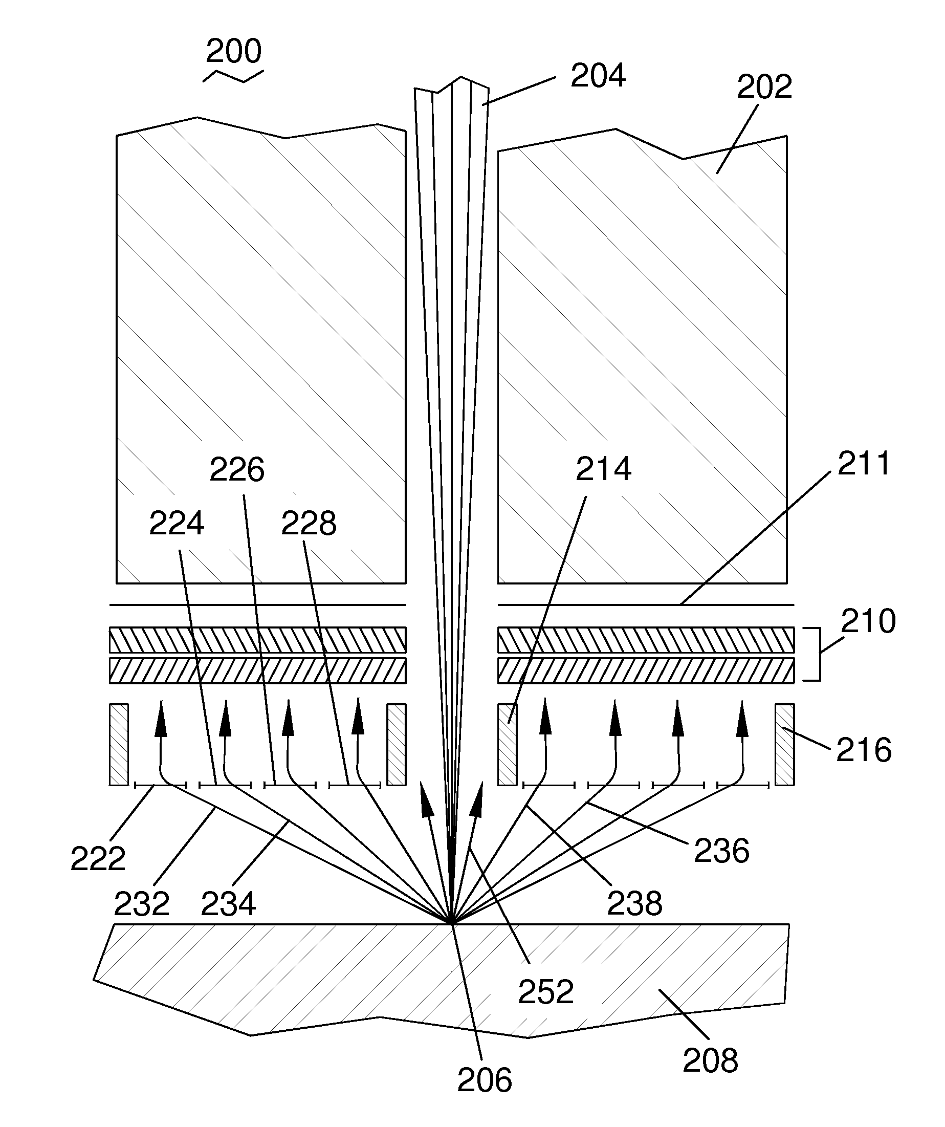
[0040]FIG. 2B shows a portion of the charged particle detector 200 of the present invention from FIG. 2A. Detector 210 is shown in a view looking up at the input signal collection surface (lower surface of detector 210 in FIG. 2A). The relative uniformity of the input signal current across the collection area of detector 210 enabled by the present invention is illustrated using uniform cross-hatched shading across the full collection area of detector 110 (compare with FIG. 1B). Three regions 240, 242, and 244, of the detector 210 at the center, middle and edge, respectively, are highlighted.

[0041]Starting at the inner edge 240 of the central hole in detector 210 (where ring 214 in FIG. 2A is attached), graph 270 is a plot of the local signal gain 272 as a function of the time-integral 271 of the output (i.e., amplified) signal current from region 240 over the lifetime of detector 210. As shown, gain curve 274 has an initial high level 276, which is maintained over a certain total ti...


PUM


Abstract

A charged particle beam system for imaging and processing targets is disclosed, comprising a charged particle column, a secondary particle detector, and a secondary particle detection grid assembly between the target and detector. In one embodiment, the grid assembly comprises a multiplicity of grids, each with a separate bias voltage, wherein the electric field between the target and the grids may be adjusted using the grid voltages to optimize the spatial distribution of secondary particles reaching the detector. Since detector lifetime is determined by the total dose accumulated at the area on the detector receiving the largest dose, detector lifetime can be increased by making the dose into the detector more spatially uniform. A single resistive grid assembly with a radial voltage gradient may replace the separate grids. A multiplicity of deflector electrodes may be located between the target and grid to enhance shaping of the electric field.

Description

TECHNICAL FIELD OF THE INVENTION[0001]The present invention relates generally to focused charged particle systems and in particular to reducing damage and contamination in detectors for secondary particles.BACKGROUND OF THE INVENTION[0002]In charged particle systems, comprising both electron microscopes and focused ion beam systems, a column is typically used to focus a charged particle beam onto the surface of a target to be imaged and (optionally) processed using the beam. To form an image of the target, it is necessary to deflect the beam across the target surface, usually in a raster pattern. Due to the impact of the charged particle beam with the target, secondary particles are emitted and may be collected to form an imaging signal. As an example, an electron beam will stimulate the emission of secondary electrons from the target. A focused ion beam will stimulate the emission of both secondary electrons and secondary ions (usually positively-charged). A secondary particle dete...

Claims


Application Information

Patent Timeline
IPC IPC(8): H01J37/147H01J37/26
CPCH01J37/244H01J37/28H01J2237/04H01J2237/04756H01J2237/0535
Inventor KNEEDLER, ERIC
Owner FEI CO
Why Eureka
Try Eureka