Method and apparatus for jitter reduction

Active Publication Date: 2012-02-16
MACOM TECH SOLUTIONS HLDG INC
View PDF12 Cites 31 Cited by
  • Summary
  • Abstract
  • Description
  • Claims
  • Application Information

AI Technical Summary

Benefits of technology

[0014]Also disclosed herein is a system for reproducing a clock signal to create a reproduced clock signal while minimizing jitter. This system comprises a phase interpolator configured to receive and process a high frequency clock signal and a phase adjustment signal to create a reduced jitter high frequency clock output. A phase detector is part of this system and configured to receive and

Problems solved by technology

One unwanted characteristic of clock distribution and data communication is signal jitter.
Thus, after a clock signal leaves the clock signal source, it is affect by channel distortion, noise and other interference.
This results in changes in its phase, also known as jitter or phase distortion.
Jitter in a clock signal or any signal affects the ability of the system to properly synchronize that signal with other signals and systems.
For example, an analog to digital converter when presented with a jitter affected clock signal will make signal output decisions when digitizing the analog input signal at an improper time whic

Method used


Image

  • Method and apparatus for jitter reduction
  • Method and apparatus for jitter reduction
  • Method and apparatus for jitter reduction

Examples


Embodiment Construction

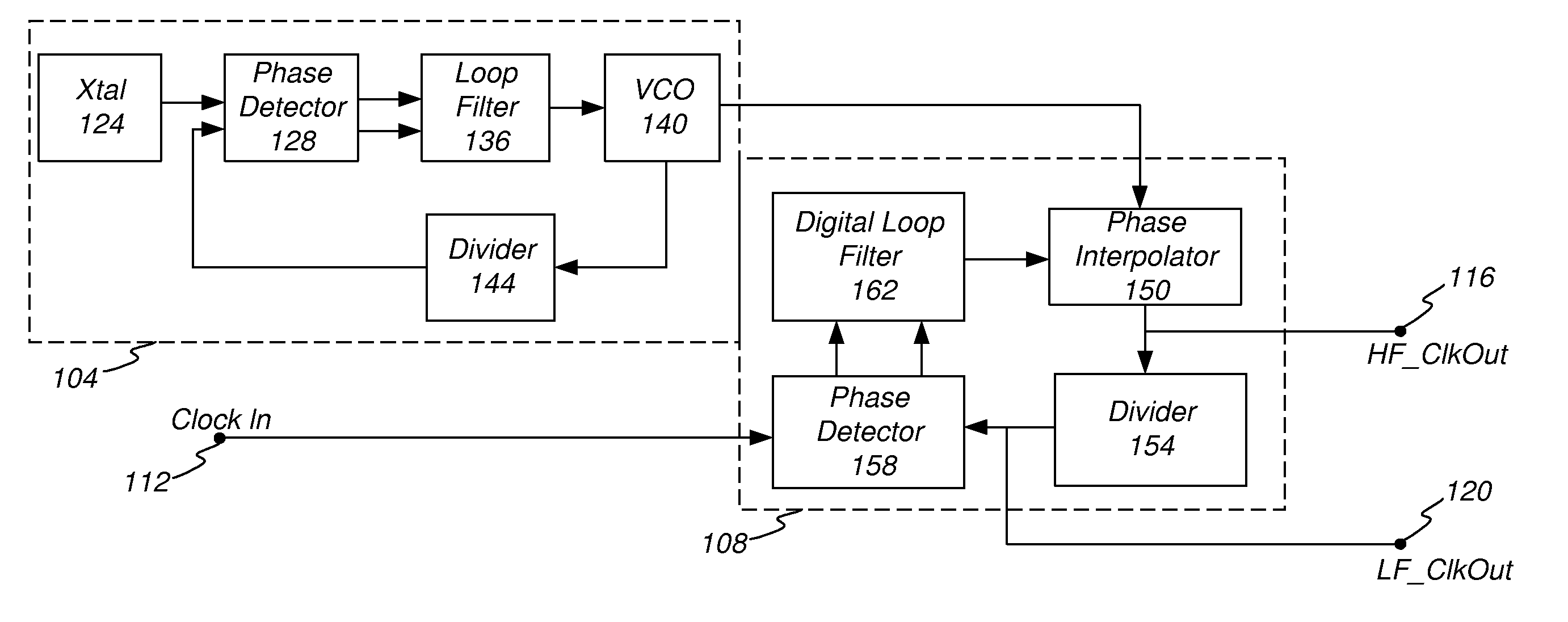
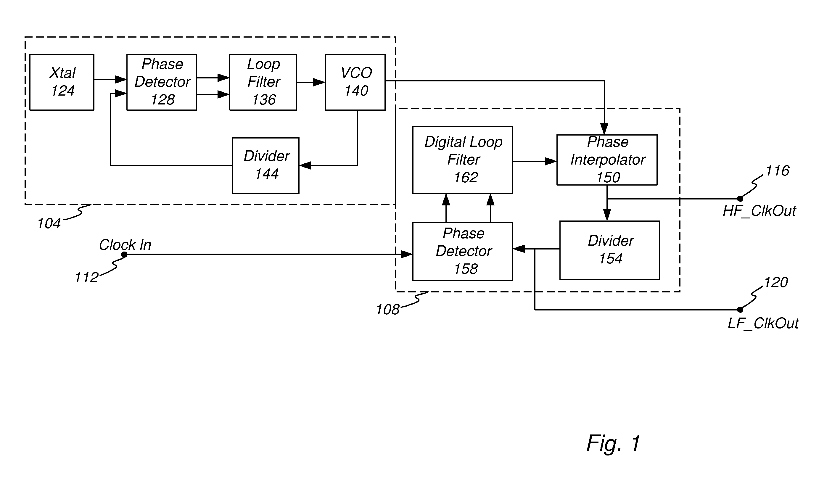
[0023]To overcome the drawbacks of the prior art and provide additional benefits, disclosed herein is a low bandwidth phase-locked loop (PLL) arranged in a dual-loop approach. In one embodiment, the first loop is a standard CMU (clock multiplier unit) using a crystal oscillator as a reference clock. The loop parameters for this first PLL can be optimized to work over a wide range of output frequencies, and with a minimum amount of jitter.

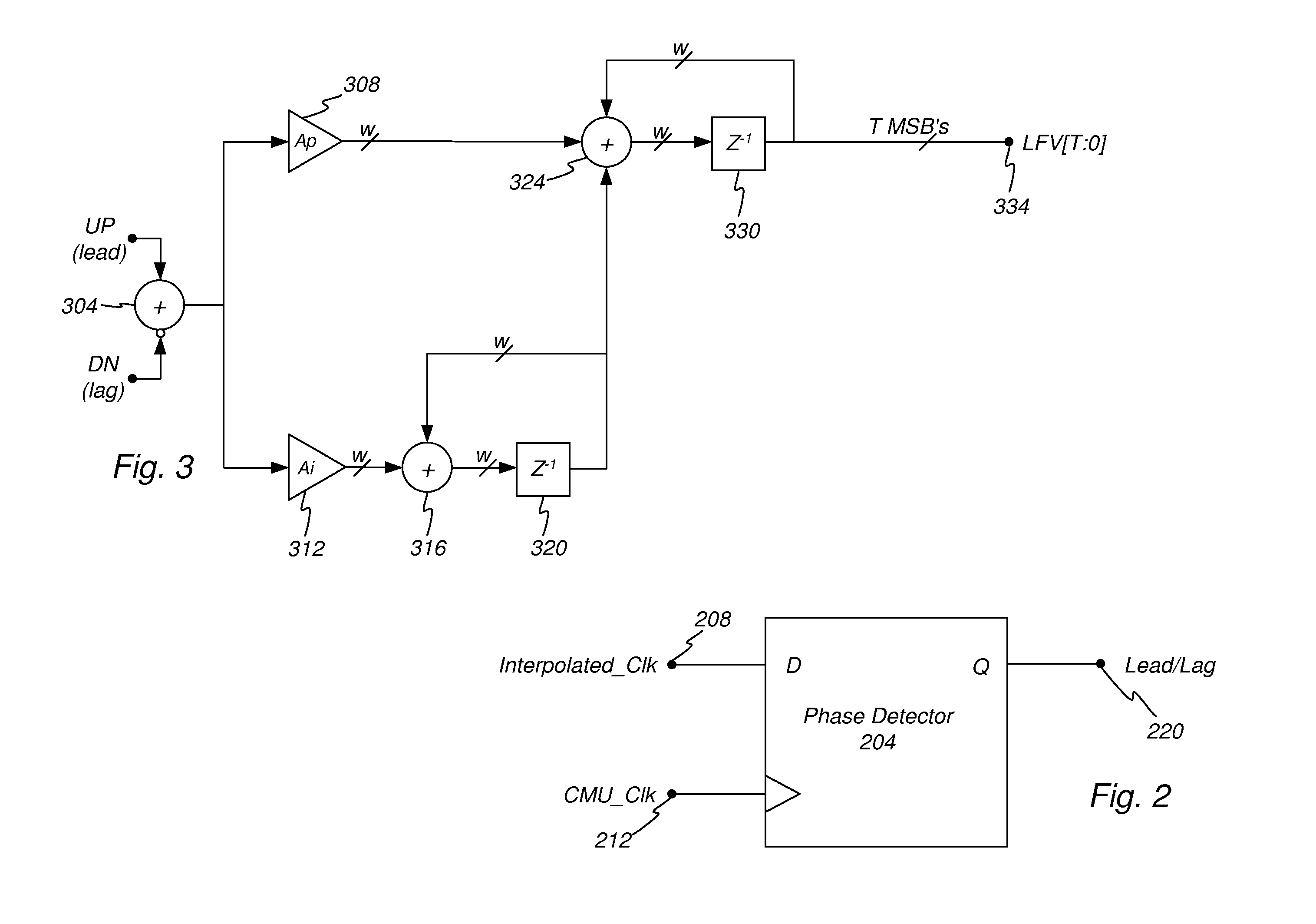
[0024]As part of the dual loop arrangement, a second loop is provided. In one embodiment the second loop comprises a bang-bang detector to drive a digital loop filter, which then drives a phase interpolator 150. The phase interpolator 150 may also comprise a mixer, or phase shifter. The phase interpolator 150 manipulates the output phase. Since phase and frequency are related (frequency is the derivative of phase), small frequency offsets (less than 5000 PPM) can be dealt with. It is this inner loop (second loop) which sets the jitter transfer bandw...


PUM


Abstract

A low bandwidth phase lock loop (PLL) arranged in a dual-loop configuration is disclosed. The first loop is a standard loop configuration using a crystal oscillator as a reference clock. The loop parameters for this first PLL can be optimized to work over a wide range of output frequencies, and with a minimum amount of jitter. The first loop outputs a reference signal, which is a VCO output. The second loop comprises a bang-bang detector configured to drive a digital loop filter, which then drives a phase interpolator. The phase interpolator manipulates the output phase. Since phase and frequency are related, where frequency is the derivative of phase, small frequency offsets can be made using a phase control signal, generated within the second loop based on the relation between the reference signal and the clock input signal. The second loop sets the jitter transfer bandwidth of the system.

Description

1. FIELD OF THE INVENTION[0001]The invention relates to reducing jitter and in particular to a jitter reducing phase lock loop circuit.2. RELATED ART[0002]Numerous types of modern professional and consumer electronic devices and most all communication system utilized one or more clock signals to syncronize operation between its various systems. Often there is a central system clock which synchronizes operation between the different subsystems with a single device or between remote communication stations. As is understood, modern electronic devices, such as cameras, video recorders, telephones, computers, TV, and other consumer electronics have numerous subsystems which must exchange data and maintain synchronization. The central clock is often distributed to numerous different sub-systems over a bus or clock signal path. Likewise, synchronization between communication devices is likewise essential to operation.[0003]Not only is clock synchronization necessary, but the performance de...

Claims


Application Information

Patent Timeline
IPC IPC(8): H03L7/08
CPCH03L7/0814H03L7/093H03L7/23
Inventor TALAGA, JR., RON F.
Owner MACOM TECH SOLUTIONS HLDG INC
Why Eureka
Try Eureka