Reducing Crimping Damage to Polymer Scaffold

a polymer scaffold and crimping technology, applied in the field of drugeluting medical devices, can solve the problems of frequent damage to the scaffold structure, the metal edge of the blade will permanently deform the strut, and the inability to use the cylindrical sheath cover, so as to reduce damage, improve batch yield, and improve the effect of significant improvemen

Active Publication Date: 2012-02-23
ABBOTT CARDIOVASCULAR
View PDF1 Cites 149 Cited by
  • Summary
  • Abstract
  • Description
  • Claims
  • Application Information

AI Technical Summary

Benefits of technology

[0014]The invention provides a process and apparatus for crimping a polymer scaffold to a balloon. The polymer scaffold is expanded for placement within a lumen of the body by plastic deformation of the polymer scaffold. The crimping process used to place the scaffold on the balloon includes, in one embodiment, an initial diameter reduction followed by final crimp steps. In one respect, the invention provides both a modified crimping apparatus and a mod

Problems solved by technology

When a polymer scaffold is placed in a crimping device for metallic stents, there is frequently occurring damage done to the scaffold structure by the forces acting on the surfaces of the scaffold through crimper blades as the scaffold is crimped to the balloon.
As such, when a metal surface of a blade bears down on surfaces of the scaffold there is likelihood that the metal edge of the blade will permanently deform the strut by the formation of indentations, cuts or gouges in the polymer material.
However, when the diameter reduction is beyond a certain amount, a cylindrical sheath covering cannot be used.
This behavior by the sheath covering would cause more troubles than it was intended to solve.
Polymer scaffolds are also more susceptible to irregular crimping forces that result in bent, twi

Method used


Image

  • Reducing Crimping Damage to Polymer Scaffold
  • Reducing Crimping Damage to Polymer Scaffold
  • Reducing Crimping Damage to Polymer Scaffold

Examples


examples

[0071]The crimping sequence for a 3.0×18 mm PLLA scaffold having the pattern illustrated in FIG. 5 is illustrated as an example. The initial pre-crimp moves the blades forming the iris from a starting diameter of 0.136 in to a diameter of 0.083 in where it remains for a 30 second dwell. This is stage 1. During this stage balloon pressure may be applied to stabilize the scaffold, in an amount of about 2 to 15 psi. The scaffold and balloon upon which the scaffold rests is then removed from the crimper and the alignment with balloon markers verified. The diameter reduction to 0.082 in loosely secures the scaffold to the balloon so that it can hold its place but is still capable of being adjusted relative to balloon markers. The scaffold is returned to the crimper.

[0072]Stage 2 of the crimping sequence moves the blades forming the iris from to a 0.068 in and is held for 15 seconds. During this stage, the balloon is inflated to about 17 to 100 psi. After this stage is complete, the ballo...


PUM

PropertyMeasurementUnit
Temperatureaaaaaaaaaa
Fractionaaaaaaaaaa

Abstract

A medical device includes a polymer scaffold crimped to a catheter having an expansion balloon. The scaffold is crimped to the catheter by a multi-step process for increasing scaffold-catheter yield following a crimping sequence. Damage reduction during a crimping sequence includes modifying blades of a crimper, adopting a multi-step crimping sequence, and inflating a supporting balloon to support the scaffold during crimping.

Description

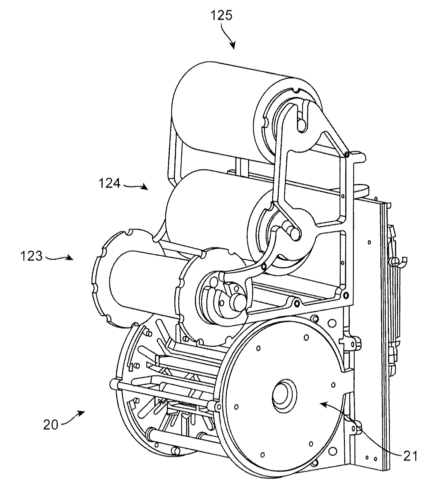
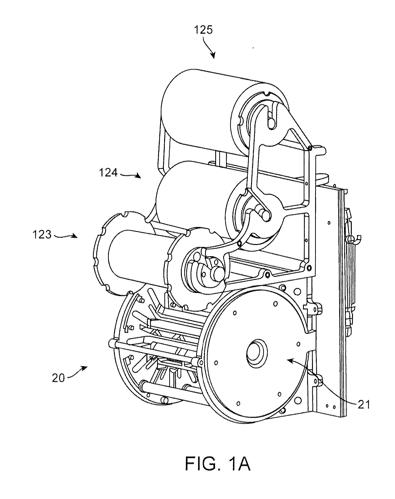
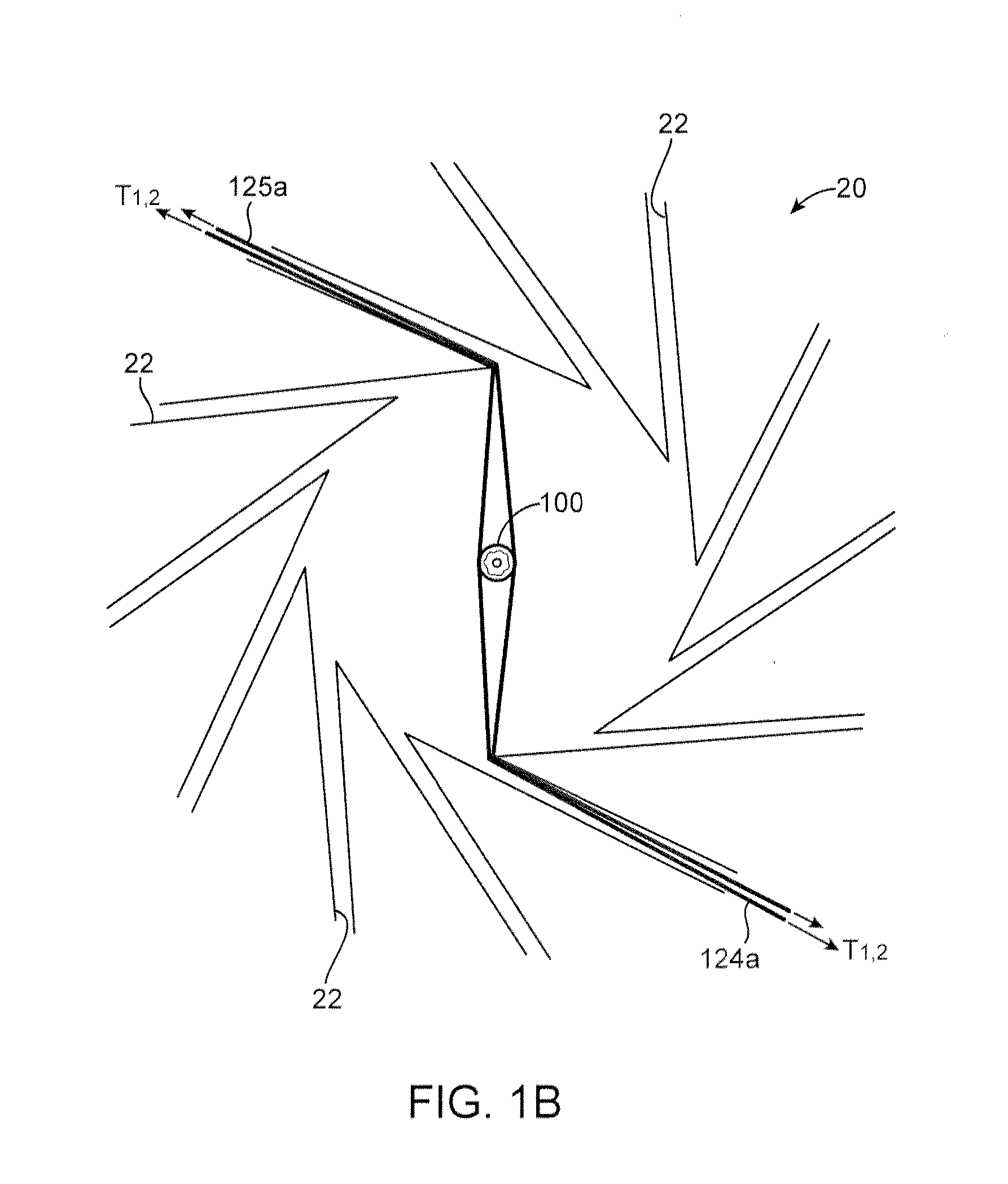
BACKGROUND OF THE INVENTION[0001]1. Field of the Invention[0002]The present invention relates to drug-eluting medical devices; more particularly, this invention relates to processes for crimping a polymeric scaffold to a delivery balloon.[0003]2. Background of the Invention[0004]Referring to FIG. 1A, there is shown a perspective view of a crimping assembly 20 that includes three rolls 123, 124, 125 used to position a clean sheet of non-stick material between the crimping blades and a metal stent prior to crimping. For example, upper roll 125 holds the sheet secured to a backing sheet. The sheet is drawn from the backing sheet by a rotating mechanism (not shown) within the crimper head 20. A second sheet is dispensed from the mid roll 124. After crimping, the first and second (used) sheets are collected by the lower roll 123. As an alternative to rollers dispensing a non-stick sheet, each metal stent may be covered in a thin, compliant protective sheath before crimping.[0005]FIG. 1B ...

Claims


Application Information

Patent Timeline
IPC IPC(8): B23P11/00B23Q1/00
CPCA61F2/95A61F2002/9522A61F2250/0067B29D23/00A61F2/958Y10T29/53996Y10T29/4994Y10T29/49925Y10T29/49945Y10T29/49908Y10T29/49927A61F2002/9583A61F2002/9586A61F2210/00A61F2240/001A61F2/9522A61F2/9524A61F2002/91566B29C67/0014B29D23/001A61F2/82B29C53/30
Inventor WANG, YUNBINGVAZQUEZ, LUISNGUYEN, HUNG T.MUELLER, SCOTT H.YAN, KATHLEEN
Owner ABBOTT CARDIOVASCULAR
Why Eureka
Try Eureka