Desulfurization and Sulfone Removal Using A Coker

a technology of desulfurization and coker, which is applied in the petroleum industry, coking carbonaceous materials, and refining with oxygen compounds, etc., can solve the problems of high vapor pressure, high vapor pressure, and high cost, and achieve high purity

a technology of desulfurization and coker, which is applied in the petroleum industry, coking carbonaceous materials, and refining with oxygen compounds, etc., can solve the problems of high vapor pressure, high vapor pressure, and high cost, and achieve high purity

US20120055845A1Active Publication Date: 2012-03-08SAUDI ARABIAN OIL CO

Image

  • Desulfurization and Sulfone Removal Using A Coker
  • Desulfurization and Sulfone Removal Using A Coker
  • Desulfurization and Sulfone Removal Using A Coker

Examples


example

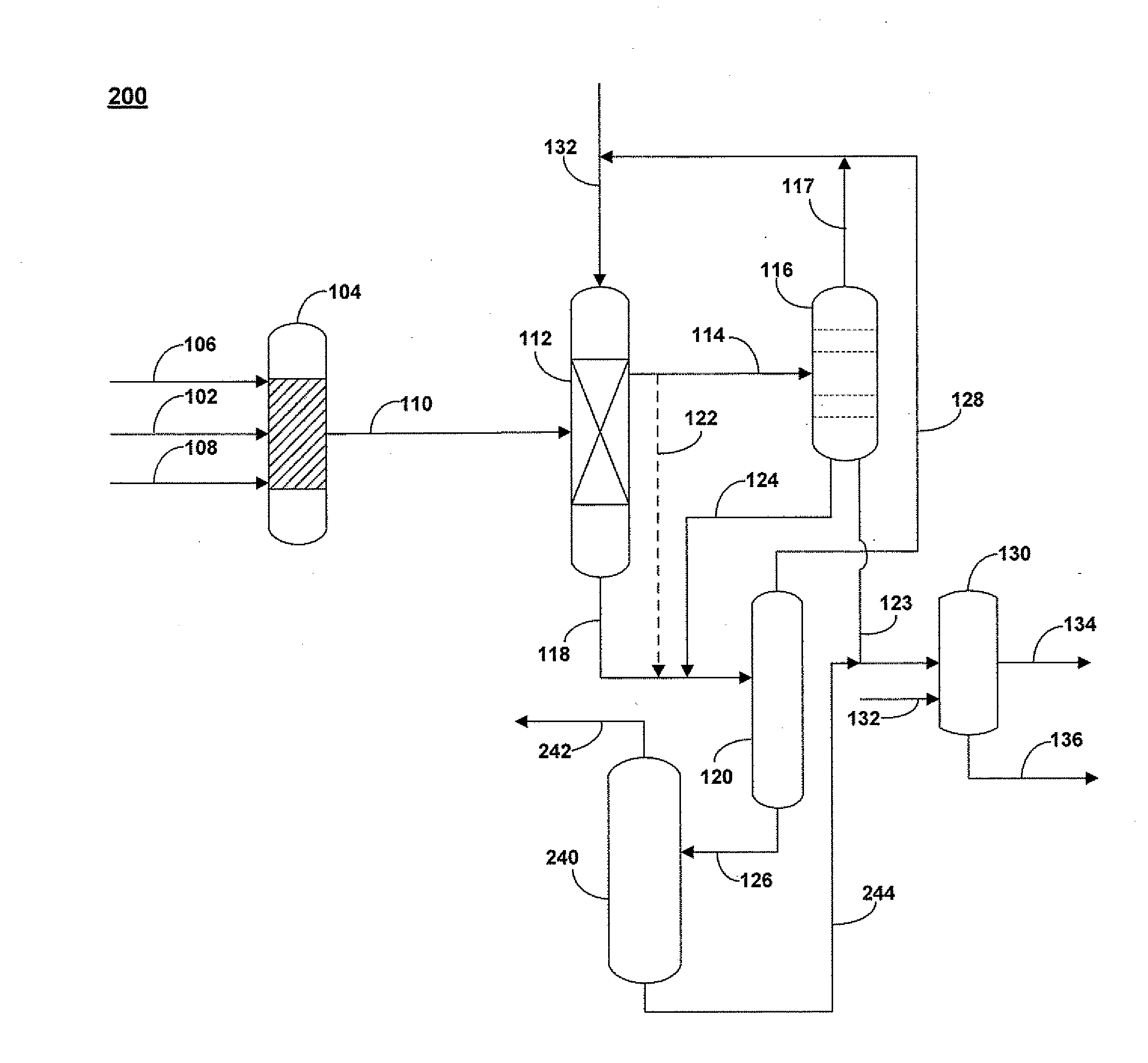
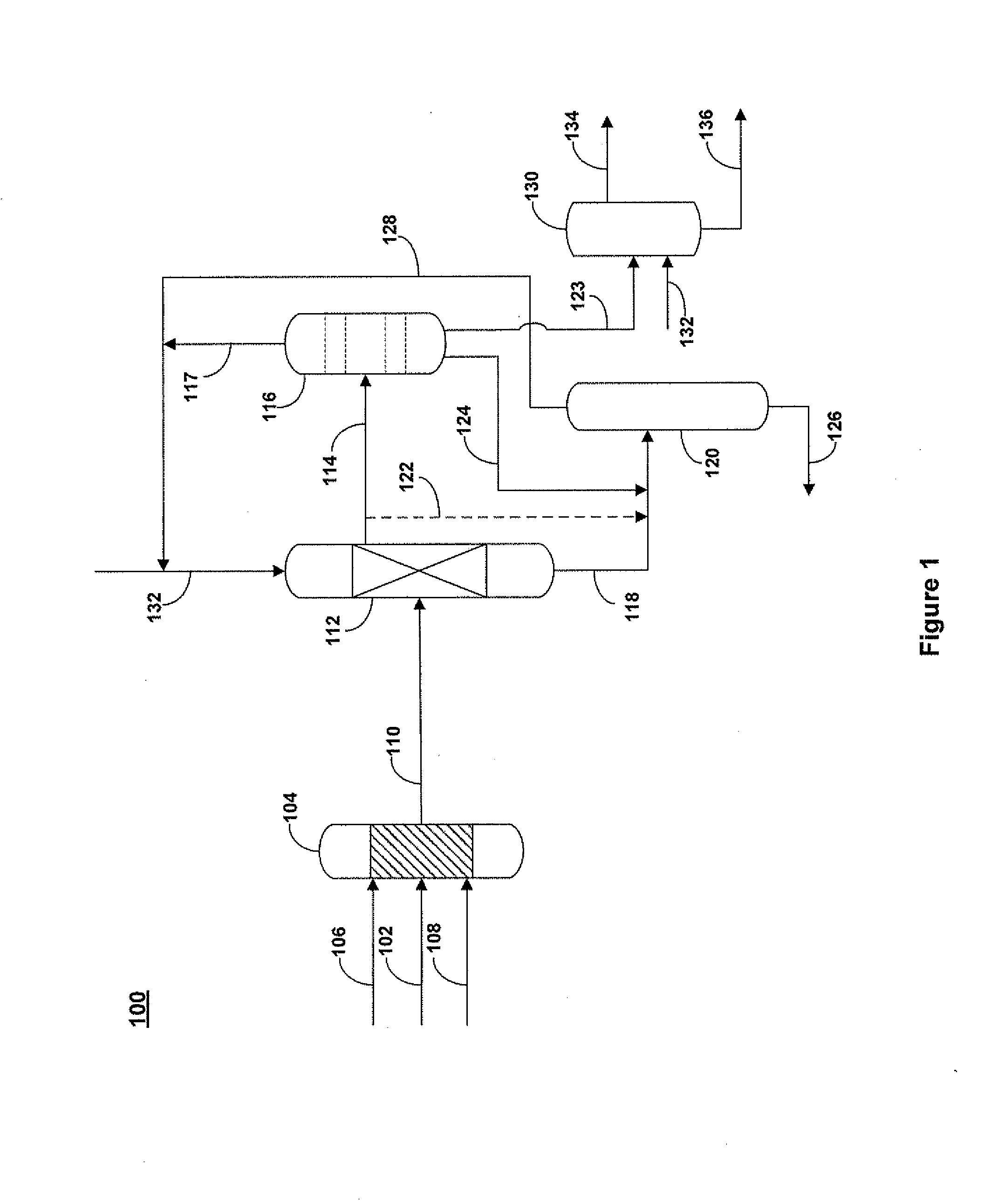
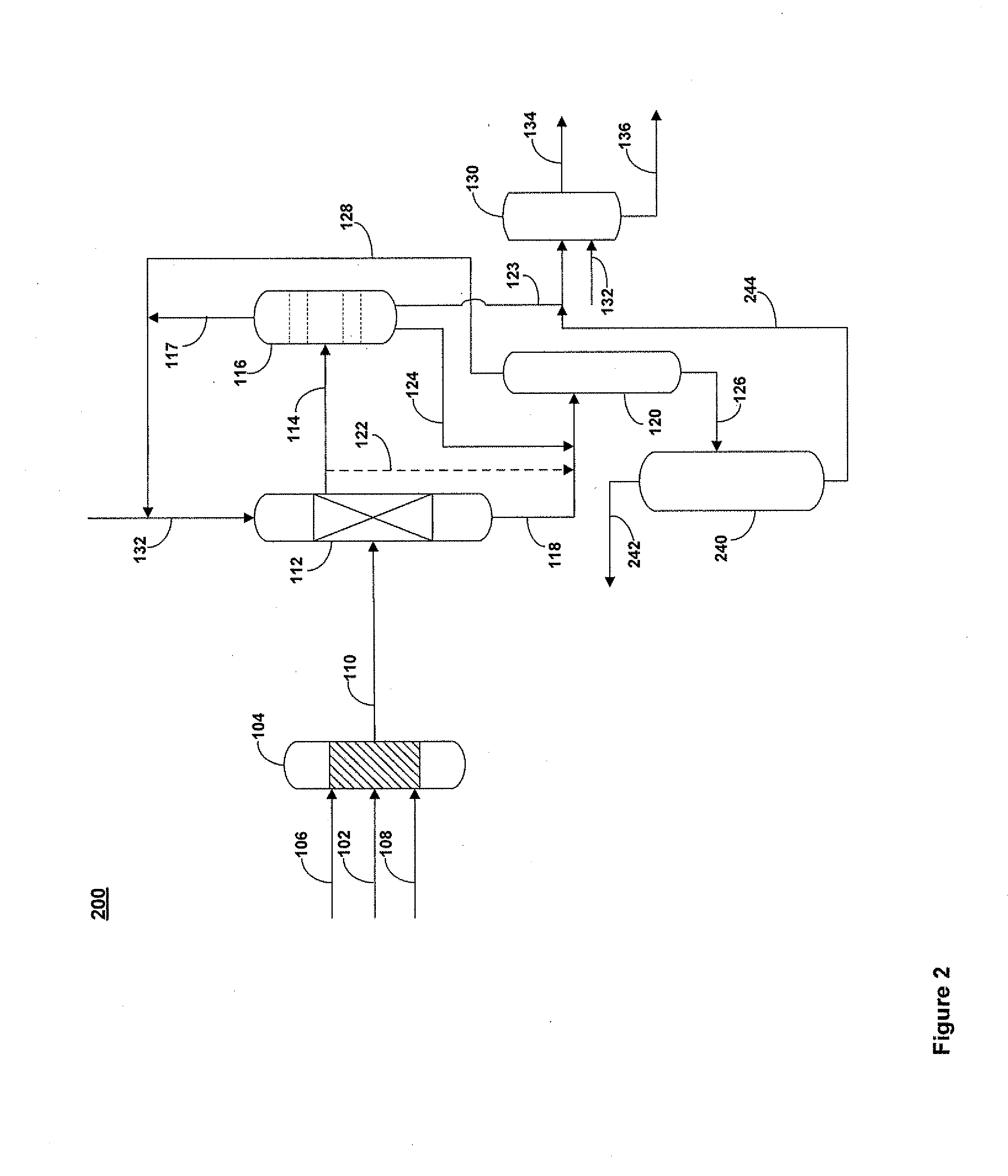
[0059]In one example, a hydrotreated straight run diesel stream 102 containing 500 ppmw of elemental sulfur 0.28 W % of organic sulfur density of 0.85 Kg / lt was oxidatively desulfurized. The oxidized and extracted sulfur compounds are mixed with a residue stream feed stream 136, properties of which are shown in Table 1, and the combined stream was supplied to the coker.

TABLE 1PropertyValueAPI Gravity4.6Specific Gravity1.04Sulfur Content, wt. %5.42Nitrogen Content, wt. %0.437Oxygen Content, wt. %0.1CCR, wt. %24.6C5 - Asphaltenes, wt. %23.5Nickel, ppmw44Vanadium, ppmw162

[0060]The reaction conditions were as follows: the mole ratio of hydrogen peroxide to sulfur was 4:1. The catalyst was a Molybdenum (VI) based catalyst. The reaction time was 30 minutes. The temperature was maintained at about 80° C., and the pressure was maintained at about 1 Kg / cm2. The coker was operated at a temperature of about 482° C. and a pressure of about 1 Kg / cm2. Material balances for the oxidation step are ...


PUM

PropertyMeasurementUnit
pressureaaaaaaaaaa
temperatureaaaaaaaaaa

Abstract

A method and apparatus for upgrading a hydrocarbon feedstock is provided. The method includes the steps of (a) supplying a hydrocarbon feedstock to an oxidation reactor, wherein the hydrocarbon feedstock is oxidized in the presence of a catalyst under conditions sufficient to selectively oxidize sulfur compounds present in the hydrocarbon feedstock; (c) separating the hydrocarbons and the oxidized sulfur compounds by solvent extraction; (d) collecting a residue stream that includes the oxidized sulfur compounds; and (e) supplying the residue stream to a coker to produce coker gases and solid coke.

Description

FIELD OF THE INVENTION [0001]This invention relates to a method and apparatus for desulfurizing a hydrocarbon feedstock. More specifically, the present invention relates to a method and apparatus for desulfurization of a hydrocarbon feedstock by oxidative desulfurization of the hydrocarbon feedstock and the subsequent treatment of oxidized sulfur and nitrogen containing species with a coker.BACKGROUND OF THE INVENTION[0002]Crude oil is the world's main source of hydrocarbons used as fuel and petrochemical feedstock. At the same time, petroleum and petroleum based products are also a major source for air and water pollution today. To address growing concerns surrounding pollution caused by petroleum and petroleum based products, many countries have implemented strict regulations on petroleum products, particularly on petroleum refining operations and the allowable concentrations of specific pollutants in fuels, such as the allowable sulfur and nitrogen content in gasoline fuels. Whil...

Claims


Application Information

Patent Timeline
08 Mar 2012
Publication
US20120055845A1
IPC
C10G17/02; C10G17/00
CPC
C10B55/00; C10B57/04; C10G21/16; C10G21/20; C10G21/22; C10G21/28; C10G2300/44; C10G27/12
Inventors
BOURANE, ABDENNOUR; KOSEOGLU, OMER REFA