Improved method and apparatus for froth flotation in a vessel with agitation

a technology of agitation and flotation vessel, which is applied in the direction of flotation, evaporator with heating coil, solid separation, etc., can solve the problems of particle detachment from the bubble, inability to recover the maximum size of particles efficiently, and large centrifugal force, so as to improve the efficiency of flotation and reduce the volume fraction of particles , the effect of low hydraulic resistan

Inactive Publication Date: 2012-03-15
NEWCASTE INNOVATION LTD
View PDF13 Cites 12 Cited by
  • Summary
  • Abstract
  • Description
  • Claims
  • Application Information

AI Technical Summary

Benefits of technology

[0052]The volumetric fraction of particles in a packed bed where the particles touch and support each other, is usually in the range 0.4 to 0.7. When the bed becomes fluidized, the particles separate from each other and the volume fraction of particles decreases. If the bed is uniform and the volume fraction is constant throughout, the Reynolds number of the flow between the particles is typically well within the laminar flow regime. Accordingly, the flow is quiescent and turbulence is absent. However, in practical liquid-fluidized beds it is difficult to maintain uniformity, and vertical channels tend to develop that allow the suspending fluid to bypass the bed. Once formed, a channel offers a low hydraulic resistance to the flow of the water through the bed, than does the bed itself, and the water that should be supporting the particles in the fluidized bed is instead diverted to flow through the channel, preventing the bed from being uniformly fluidized. When air bubbles are introduced, channel formation is further enhanced.

Problems solved by technology

Greater rotational speeds lead to larger centrifugal forces that tend to cause the particles to detach from the bubbles.
Accordingly, in mechanical cells in current practice, there is an inherent limitation in the maximum size of particles that can be recovered efficiently.
An inherent difficulty with mechanical cells is that as the particle size increases, greater turbulent energy must be supplied to keep the particles in suspension in the cell, thereby leading to less and less likelihood that the coarse particles will be able to remain attached to the bubbles.
It is evident that the level of turbulence in such cells is so high that coarse particles are detached from spinning bubbles, leading to low recoveries in the coarse size fractions.

Method used


Image

  • Improved method and apparatus for froth flotation in a vessel with agitation
  • Improved method and apparatus for froth flotation in a vessel with agitation
  • Improved method and apparatus for froth flotation in a vessel with agitation

Examples


example

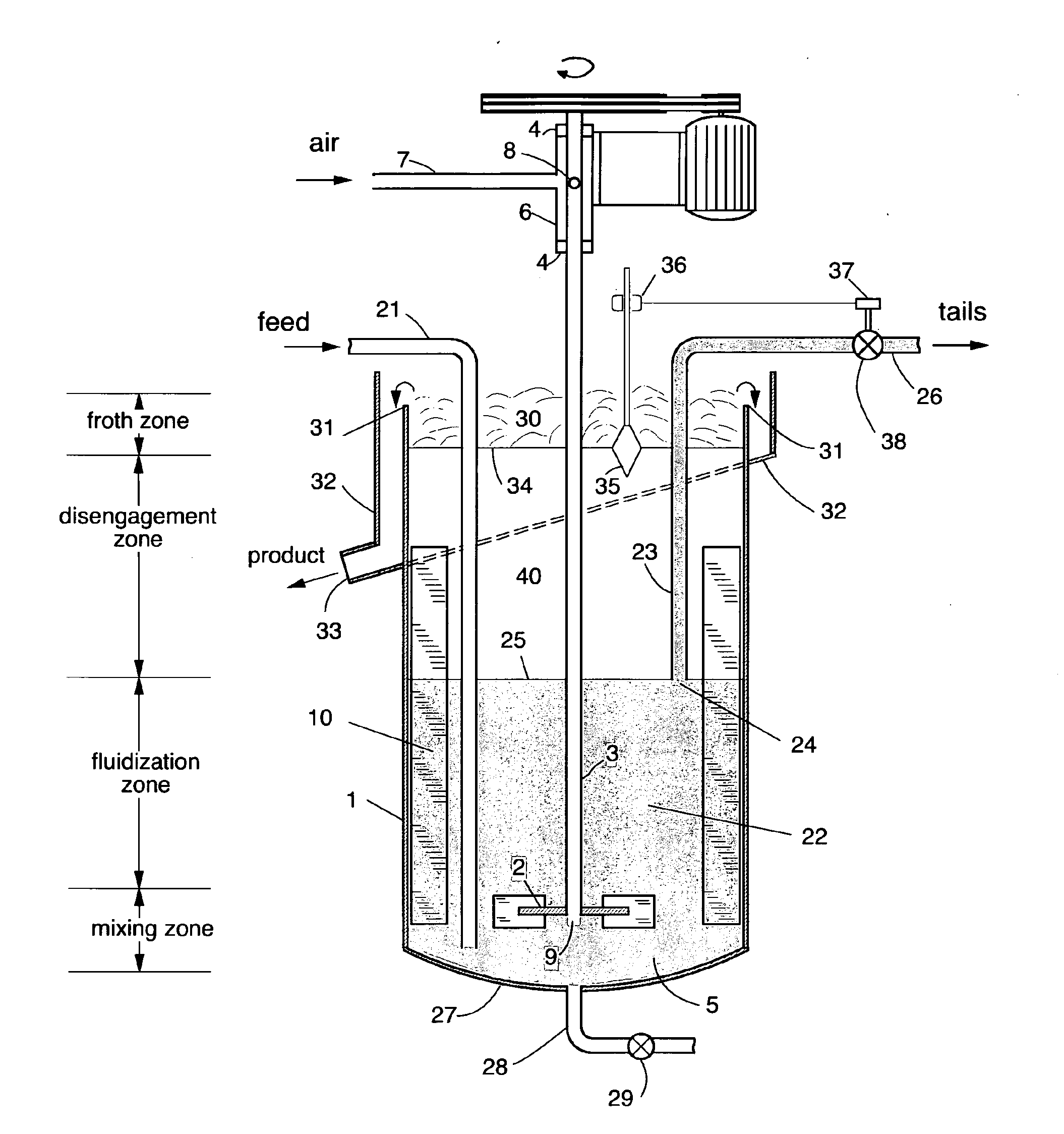
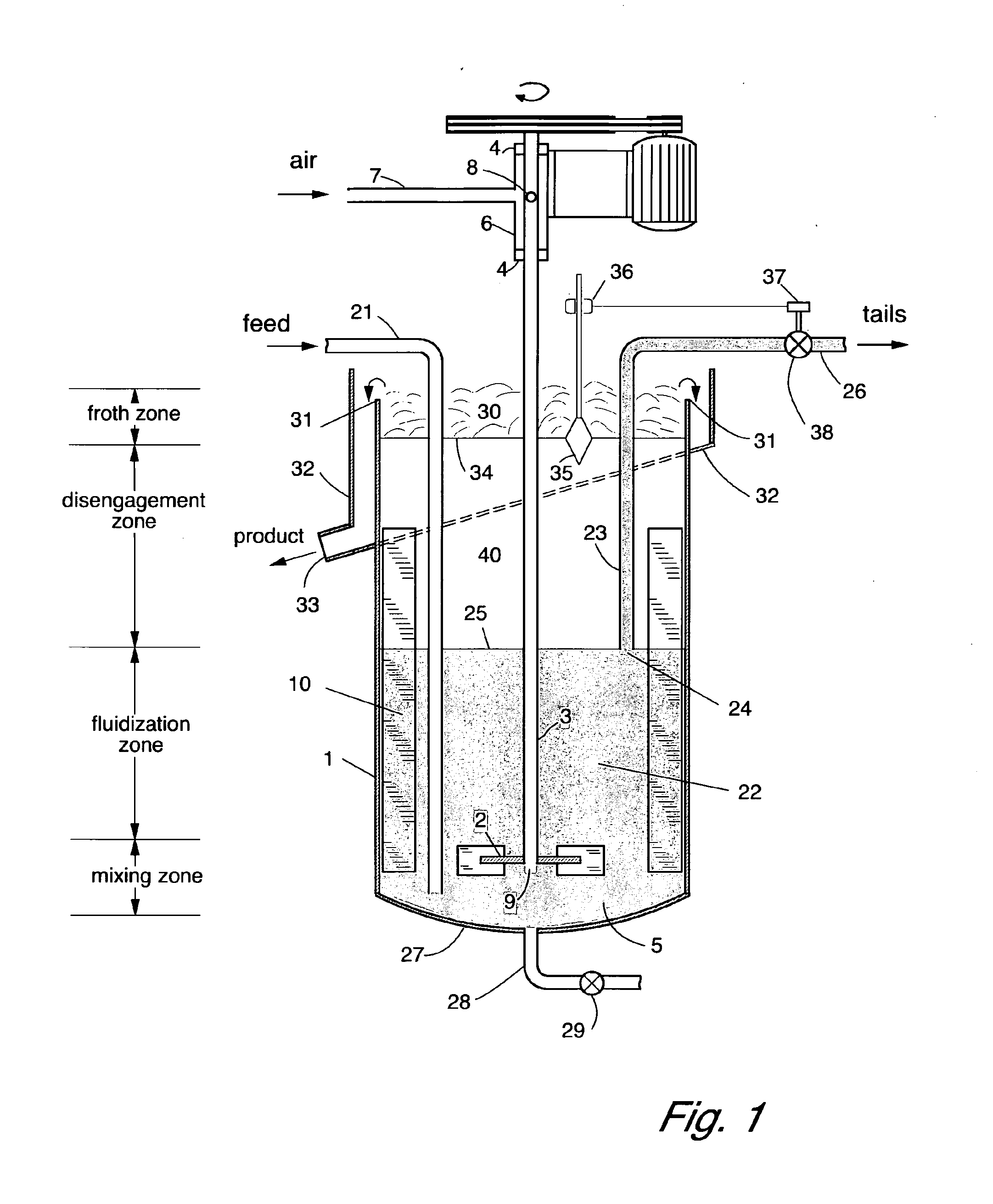
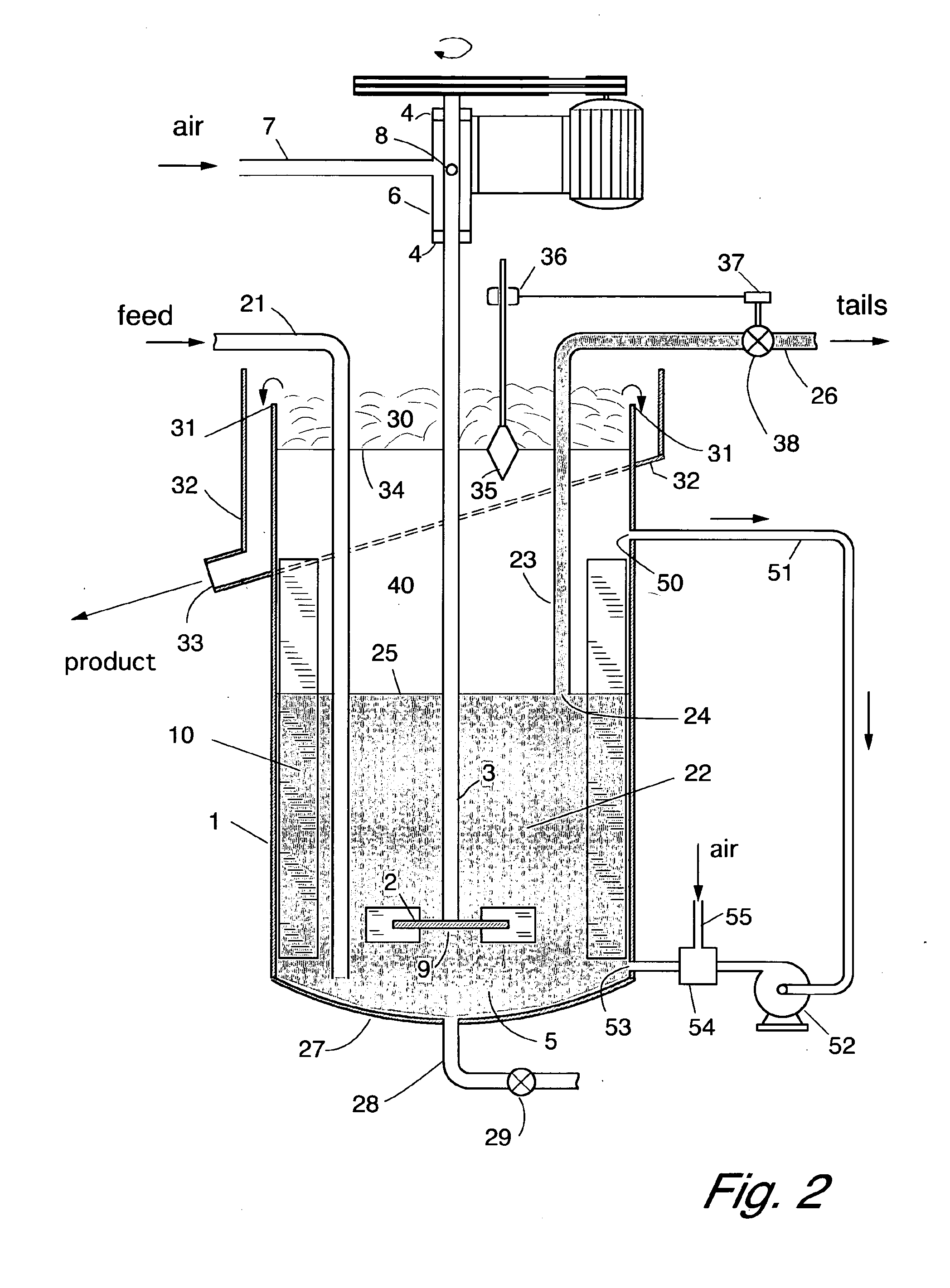
[0078]A flotation cell was constructed according to the invention, and operated in batch mode. A sample of high-grade galena was used as the floatable material, and it was mixed with graded silica particles as a source of non-floatable material. The galena was crushed and sieved to provide a sample in the size range 45 to 1400 micrometres. The silica was in the size range 250 to 710 micrometres. The galena:silica mass ratio was 1:19 and the sample volume was 1.05 litres. The cell diameter was 100 mm, with a froth zone of diameter 63 mm and height 150 mm. The overall height of the cell was 920 mm. The cell was fitted with an impeller of diameter 70 mm operating at 150 rpm, with a tip speed of 0.55 m / s. When fluidized with recirculation fluid a clear transition could be seen through the transparent cell wall, between the top of the fluidization zone and the disengagement zone. The contents of the cell were fluidized with fluid taken from the disengagement zone and recycled through a b...


PUM


Abstract

A method of separating mixed particles in a flotation cell uses a fluidized bed within the cell where particles are fluidized in a quiescent zone by liquid moving upwardly through the fluidized bed. The fluidizing liquid may be provided by the feed or by recycling liquid from upper parts of the cell such as from the disengagement zone. Bubbles are introduced into the lower part of the cell through a mechanical impeller which also breaks up any channels in the mixing zone, or by separate aeration in the bottom of the cell or by introduction through a recycle pipe.

Description

FIELD OF THE INVENTION[0001]This invention relates to the froth flotation process for the separation of particles. In particular, it relates to improving the recovery of coarse particles by froth flotation.BACKGROUND OF THE INVENTION[0002]The flotation process is used extensively in industry to separate valuable particles from particles of waste material. In the minerals industry for example, rock containing a valuable component is finely ground and suspended in water. Reagents are generally added that attach selectively to the valuable particles making them water repellent or non-wetting (hydrophobic), but leaving the unwanted particles in a wettable (hydrophilic) state. Bubbles of air are introduced into the suspension in a vessel or cell. The non-wettable particles attach to the bubbles, and rise with them to the surface of the suspension where a froth layer is formed. The froth flows out of the top of the cell carrying the flotation product. The particles that did not attach to ...

Claims


Application Information

Patent Timeline
Patent Type & Authority Applications(United States)
IPC IPC(8): B03D1/02B03D1/16B03D1/001
CPCB03D1/028B03D1/1412B03D1/1475B03D1/245B03D1/22B01D1/02B03D1/00B03D1/16
Inventor JAMESON, GRAEME JOHN
Owner NEWCASTE INNOVATION LTD
Why Eureka
Try Eureka