Fuel Injector Sans Support/Stem

a fuel injector and support/stem technology, applied in the direction of machines/engines, combustion types, lighting and heating apparatus, etc., can solve the problems of significant thermal stress on the support/stem, reducing the quality of the fuel, and reducing so as to reduce some interrelational or internal stresses, increase the modal frequency, and increase the stiffness-to-mass ratio of the fuel nozzl

Inactive Publication Date: 2012-03-15
WOODWARD GOVERNOR CO
View PDF4 Cites 0 Cited by
  • Summary
  • Abstract
  • Description
  • Claims
  • Application Information

AI Technical Summary

Benefits of technology

[0010]In view of the above, embodiments of the present invention provide a new and improved fuel nozzle for a turbine engine or other combustion engine. More particularly, embodiments of the invention provide a new and improved fuel nozzle that can be formed from standard materials that do not need to be molded, formed or otherwise exposed to expensive manufacturing processes and that can eliminate the need for the standard support / stem. Additionally, embodiments of the invention provide a new and improved fuel nozzle that can increase a stiffness-to-mass ratio of the fuel nozzle to thereby increase modal frequencies. Further, embodiments of the invention provide a new and improved fuel nozzle that reduces some of the interrelational or internal stresses due to operational conditions of the fuel nozzle. Finally, other embodiments of the invention provide a new and improved fuel nozzle that provides an improved interface between a primary heat shield and a heat shield for a tip portion of the fuel nozzle.
[0014]In yet another implementation, the support members are affixed to one another at a first end such that those ends of the plurality of support members cannot move relative to one another. However, the opposed ends of the plurality of support members are free, such that the individual tubes are free to slide relative to one another in the event that the support members are bent due to operational conditions. Additionally, the support members are free to expand and contract independently reducing the interrelational stresses and internal stresses within the support structure of the fuel tube, i.e. the plurality of support members.
[0015]In one embodiment with the support members coupled at a first end only, the fuel nozzle includes a cap that connects the ends and covers the ends of the support members. In a further preferred implementation, the fuel nozzle further includes a head portion coupled to the heat shield that is typically external to the combustion chamber in operation. In this embodiment, the cap and connected ends of the support members are preferably positioned within the head portion to further insulate the connected ends of the support members from the heat that is exposed to the fuel nozzle.

Problems solved by technology

More particularly, if too much heat is transferred to the fuel, the fuel can begin to coke, thereby ruining or reducing the quality of the fuel.
Additionally, coke deposits can form on or in the fuel injector decreasing and in some instances entirely stopping flow through the fuel injector.
Unfortunately, the support / stem is typically a solid cast, wrought, forged, machined or similarly formed piece free of thermal barriers that can allow for significant heat transfer.
Further, as the support / stem is exposed to the high-temperature compressor air, the support / stem experiences significant thermal stresses due to thermal expansion and contraction.
As the support / stem is a solid piece, the material of the support / stem is exposed to internal interrelational stresses that can fatigue the support / stem, thereby weakening the structural strength of the fuel nozzle.
Finally, because the support / stem is typically a solid cast, wrought, forged, machined or similarly manufactured component, the manufacturing costs associated therewith can be significant.
Particularly, if minor modifications to the fuel nozzle, and particularly the support / stem, are desired, new tooling and dies are often required which is costly, if not prohibitive.

Method used


Image

  • Fuel Injector Sans Support/Stem
  • Fuel Injector Sans Support/Stem
  • Fuel Injector Sans Support/Stem

Examples


Embodiment Construction

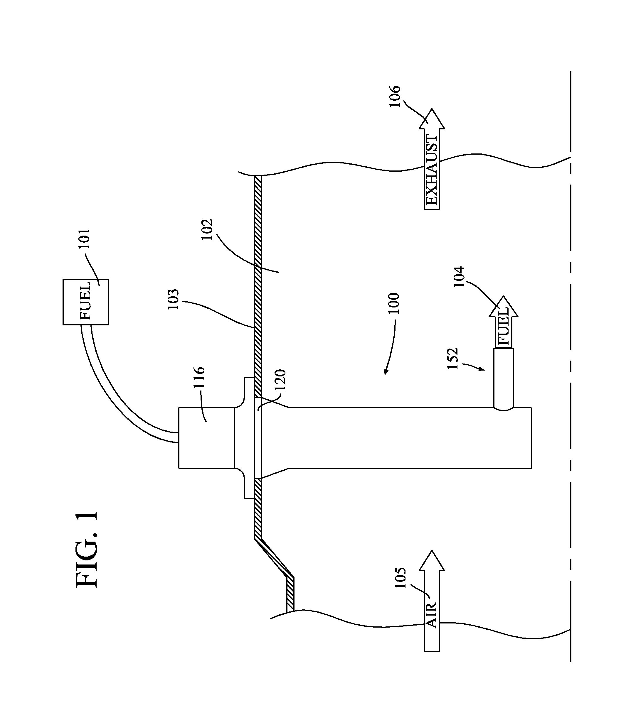
[0025]Turning now to FIG. 1, a fuel nozzle 100 is illustrated in a suitable environment for delivery of fuel that is supplied from a fuel supply 101 to a combustor or combustion chamber 102. Preferably, the combustion chamber 102, illustrated in simplified form, is the combustion chamber of a turbine engine and is bounded by boundary wall 103, also referred to as an engine case. However, the fuel nozzle 100 could be implemented in other systems requiring combustion of a fuel such as a piston driven internal combustion engine.

[0026]Fuel illustrated as arrow 104 supplied from the nozzle 100 is combusted in the combustion chamber 102 with air, illustrated as arrow 105. As is well known in the art, the combusted exhaust gasses, illustrated as arrow 106, when in a turbine environment, flow out of the combustion chamber and drive a set of turbine blades (not shown). Alternatively, in a piston engine, the expanding exhaust gasses drive the pistons. During this process, because the fuel noz...


PUM


Abstract

A fuel nozzle is provided. The fuel nozzle includes a heat shield, a fuel tube and a plurality of support members. The support members are radially interposed between the heat shield and the fuel tube. The support members are preferably cylindrical tubes, thus creating voids or pockets between the heat shield and the fuel tube. The cylindrical tubes are connected to one another at a first end are free at an opposed end. As such, the tubes can move or slide relative to one another. Further, the tubes preferably only contact one another with at most line contacts. The fuel nozzle may also include a tip portion that includes a tip heat shield that extends radially outward from the primary heat shield. The tip heat shield defines a cavity that connects with the central cavity of the heat shield. The fuel tube extends through the tip heat shield.

Description

CROSS-REFERENCE TO RELATED PATENT APPLICATION[0001]This patent application is a Continuation of co-pending U.S. patent application Ser. No. 12 / 194,597, filed Aug. 20, 2008, the teachings and disclosure of which are incorporated herein in their entireties by reference thereto.FIELD OF THE INVENTION[0002]This invention generally relates to fuel delivery systems and more particularly to fuel injectors (i.e. fuel nozzles) for delivering fuel to combustion chambers for combustion engines.BACKGROUND OF THE INVENTION[0003]Fuel injectors (a.k.a. fuel nozzles) are important components of gas turbines as well as other gas combustion engines. Because the fuel nozzle is the source of the fuel, the fuel nozzle can provide significant play in the role of engine performance.[0004]Because the fuel nozzle extends into the combustion chamber (a.k.a. the combustor), typically, a fuel nozzle includes an external support / stem through which an internal fuel tube extends. The fuel tube will be connected t...

Claims


Application Information

Patent Timeline
Patent Type & Authority Applications(United States)
IPC IPC(8): F02M53/04
CPCF02M61/145F02M53/04F23R3/283F23D11/36
Inventor SMITH, DAVID S.
Owner WOODWARD GOVERNOR CO
Why Eureka
Try Eureka