
Antenna system with planar dipole antennas and electronic apparatus having the same

a technology of electronic equipment and antenna system, which is applied in the direction of simultaneous aerial operation, electrically short antenna, and antenna, etc., can solve the problems of poor radiation directivity, time-consuming and costly, and the general range of gain values of planar inverted-f antennas is generally poor, so as to achieve high gain and high directionality

Active Publication Date: 2012-03-15
LITE ON ELECTRONICS (GUANGZHOU) LTD +1
View PDF4 Cites 13 Cited by
  • Summary
  • Abstract
  • Description
  • Claims
  • Application Information

AI Technical Summary

Benefits of technology

[0007]Therefore, an object of the present invention is to provide a multi-band antenna system with high directionality and high gain.
[0008]Another object of the present invention is to provide an antenna system that is small and low cost, that has a low profile, and that is suitable for application to small wireless network products.

Problems solved by technology

M377714, are bulky and require electrical connection to additional grounding planes.
On the other hand, fabrication of antennas with three-dimensional metal structures generally involves multiple bending processes, which can be time-consuming and costly.
In addition, planar inverted-F antennas generally have a relatively poor range of gain values (typically about 3 dBi at 2.4 GHz and 4 dBi at 5 GHz), and are characterized by non-broadside radiation (i.e., poor radiation directivity).

Method used


Image

  • Antenna system with planar dipole antennas and electronic apparatus having the same
  • Antenna system with planar dipole antennas and electronic apparatus having the same
  • Antenna system with planar dipole antennas and electronic apparatus having the same

Examples


Embodiment Construction

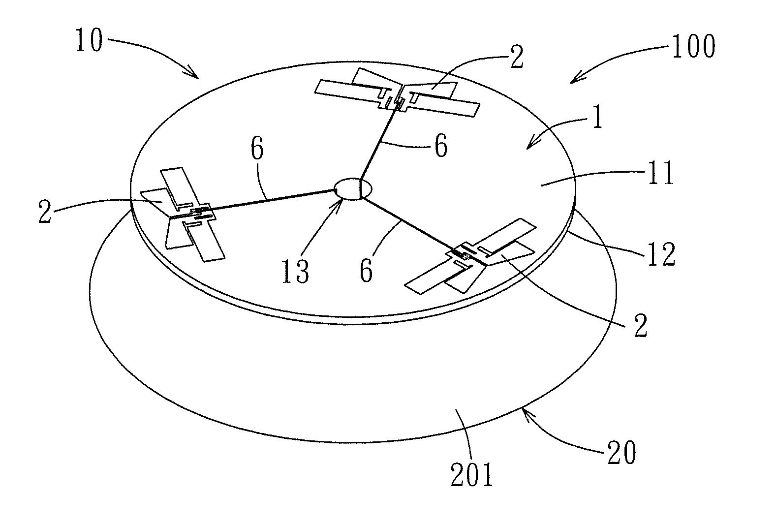
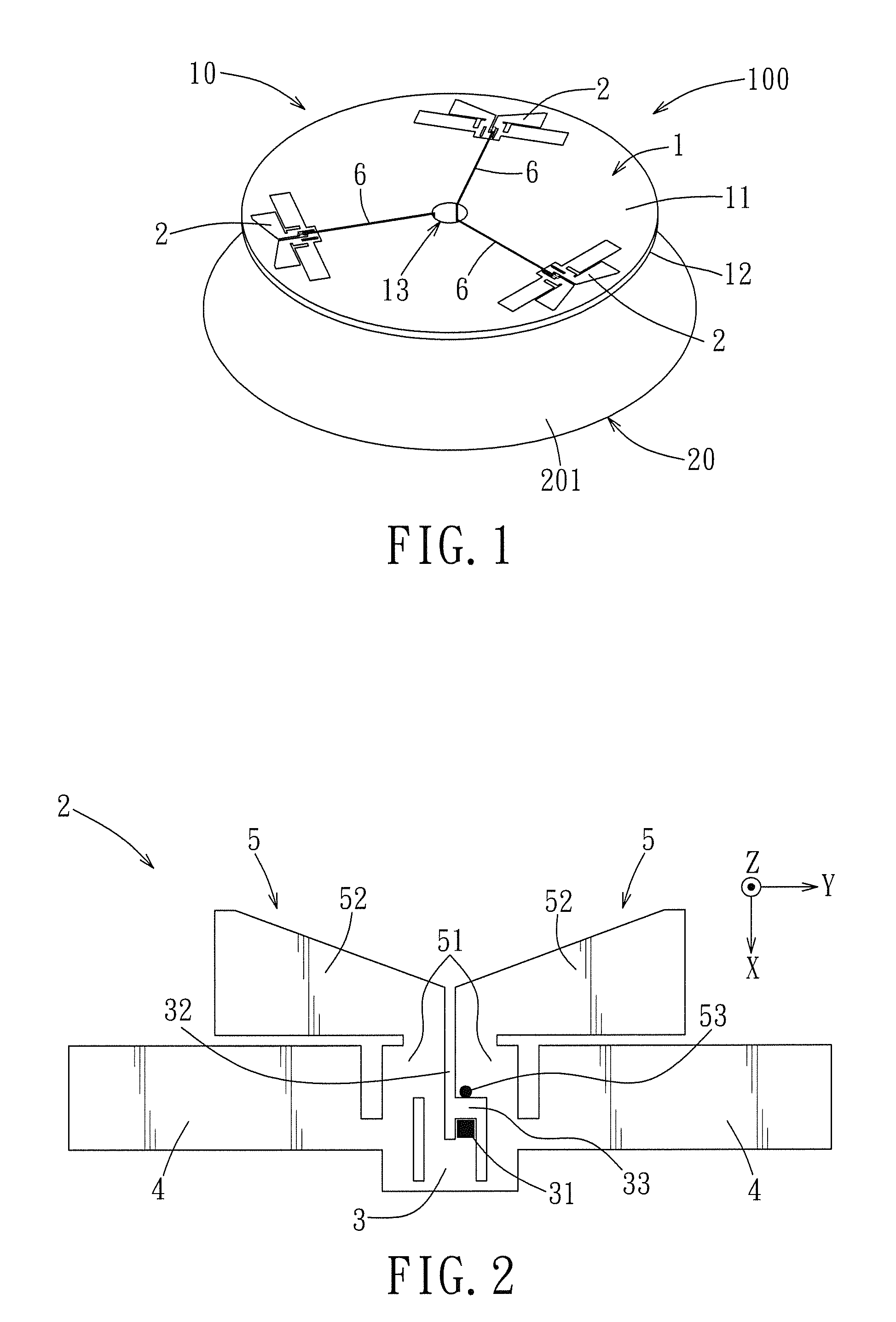
[0030]Referring to FIG. 1, the preferred embodiment of a multi-antenna system 100 according to the present invention is a planar antenna system operable in first and second frequency bands ranging from 2400 MHz to 2484 MHz and from 5150 MHz to 5825 MHz, respectively, is preferably fabricated using printed circuit board (PCB) techniques, and includes an antenna module 10 and a system module 20.

[0031]The antenna module 10 includes a substrate 1 and a plurality of planar dipole antennas 2. In this embodiment, the substrate 1 includes opposite first and second surfaces 11, 12, is formed with a through hole 13 for extension of signal-feed cables 6 therethrough, and is preferably made of dielectric materials, such as glass fiber (FR4). In addition, the antenna module 10 includes three planar dipole antennas 2 each being a half-wavelength dipole antenna. However, configuration of the planar dipole antennas 2 may be otherwise in other embodiments. Although the substrate 1 of this embodiment...


PUM


Abstract

An antenna system includes: and antenna module and a system module. The antenna module includes a substrate, and a plurality of planar dipole antennas each including a short-circuit section, two first radiator sections operable in a first frequency band and connected to the short-circuit section, and two second radiator sections operable in a second frequency band and connected to the short-circuit section. The planar dipole antennas are arranged such that geometric centers thereof are respectively spaced apart from a center point bounded by the planar dipole antennas by a predetermined distance, such that each of the planar dipole antennas is spaced apart from an adjacent one of the planar dipole antennas by a predetermined minimum distance. The system module has a grounding plane that faces toward and that is spaced apart from and parallel to the substrate.

Description

CROSS-REFERENCE TO RELATED APPLICATION[0001]This application claims priority of Chinese Application No. 201010282201.7, filed on Sep. 14, 2010.BACKGROUND OF THE INVENTION[0002]1. Field of the Invention[0003]The present invention relates to an antenna system and an electronic apparatus having the same, more particularly to an antenna system with multiple planar dipole antennas and an electronic apparatus having the same.[0004]2. Description of the Related Art[0005]Most modern wireless network products, such as wireless access points, are compact and lightweight. Therefore, how to reduce space occupied by antennas in the wireless network products without significant adverse impact to antenna performance is always among the subjects of endeavor in the antenna industry.[0006]Conventional monopole antennas, such as one disclosed in Taiwanese patent No. M377714, are bulky and require electrical connection to additional grounding planes. On the other hand, fabrication of antennas with thre...

Claims


Application Information

Patent Timeline
Patent Type & Authority Applications(United States)
IPC IPC(8): H01Q21/20H01Q21/30H01Q5/357
CPCH01Q9/285H01Q5/357H01Q21/20
Inventor HUNG, TZU-CHIEHSU, SAOU-WEN
Owner LITE ON ELECTRONICS (GUANGZHOU) LTD
Learn More