
Refrigerant circuit of an HVAC system of a motor vehicle

a technology of hvac system and refrigeration circuit, which is applied in the direction of refrigeration components, machine operation mode, light and heating apparatus, etc., can solve the problems of developing and dissipating heat, affecting the comfort of vehicles, and no longer available waste heat for heating the interior of vehicles, etc., to achieve the effect of improving efficiency, improving performance and li

Active Publication Date: 2012-04-12
AUDI AG +1
View PDF17 Cites 69 Cited by
  • Summary
  • Abstract
  • Description
  • Claims
  • Application Information

AI Technical Summary

Benefits of technology

[0015]The invention aims at providing an HVAC system for the interior of a vehicle, particularly an electric or hybrid vehicle, with the additional possibility to condition components of the electric drive train, the HVAC system demanding minimum electric power for operation, thus providing a greatest possible electric power for a maximum range of the vehicle. Further, using several heat sources and heat sinks, the system is intended to be efficiently operatable and designed compact in order to minimize the space required within the vehicle. In this way, it is intended to minimize the operating costs, the costs of manufacture, and the servicing costs. In addition, it is intended to avoid negative safety effects during operation of the system.
[0019]The arrangement according to the invention of the components within the refrigerant circuit enables for conditioning the fresh air to be fed into the vehicle interior switching over between a heating mode and a cooling mode and, further, an advantageous reheating mode of the refrigerant circuit of the HVAC system.
[0027]Further, it is advantageous to configure the primary circuit provided with an internal heat exchanger, wherein the internal heat exchanger is positioned on the high pressure side in the direction of flow of the refrigerant subsequent to the connection point preferentially established as collector, on the low pressure side in the direction of flow of the refrigerant previous to the compressor. Therefore, it is possible to transmit heat between the liquid refrigerant at high pressure and the gaseous refrigerant at low pressure within the primary circuit, that is internal to the refrigerant circuit. Hereby liquid refrigerant is overcooled after condensation, or at the outflow of the collector, respectively, and at the same time the suction gas drawn in by the compressor is overheated.
[0046]The solution according to the invention has various advantages: conditioning, particularly cooling, dehumidifying and / or heating of the vehicle interior at minimum effort of electric energy, with use of waste heat flows for heating the vehicle interior, cooling of the components of the drive train of the vehicle, such as the battery, the electric motor and the power electronics, resulting in increased performance, efficiency, and life of the components, providing of a comfort in the passenger compartment at the same level known of engine-driven vehicles, ensuring the maximum range of electric vehicles with same battery capacity, particularly under extreme climatic conditions, also by reduction of the required battery capacity for auxiliaries, accompanied with reduction of weight, cost reduction, and saving of limited resources such as lithium.

Problems solved by technology

The trend towards high-efficiency, environment-friendly drive systems for motor vehicles means that sufficient waste heat for heating the vehicle interior is no longer available.
Due to less waste heat and the lower temperature level of the refrigerant circuit that cools the drive train, the comfort conditions worsen in vehicles with the heating of the vehicle interior exclusively based on the engine refrigerant circuit.
The developed and released heat is to be dissipated, because an increased temperature of operation causes a very high thermal load of the battery cells.
Because of the limited temperature stability of the batteries, they have to be actively cooled.
When this heat exchanger is afterwards used for heating again, a highly undesirable effect dangerous in relation to safety arises.
The high humidity content in the air supplied to the vehicle interior causes precipitation at the cold surfaces in the vehicle interior, particularly, fogging of the window glasses with accompanying worsening of the passengers' vision.

Method used


Image

  • Refrigerant circuit of an HVAC system of a motor vehicle
  • Refrigerant circuit of an HVAC system of a motor vehicle
  • Refrigerant circuit of an HVAC system of a motor vehicle

Examples


Embodiment Construction

[0056]The following detailed description and appended drawings describe and illustrate various embodiments of the invention. The description and drawings serve to enable one skilled in the art to make and use the invention, and are not intended to limit the scope of the invention in any manner. In respect of the methods disclosed, the steps presented are exemplary in nature, and thus, the order of the steps is not necessary or critical.

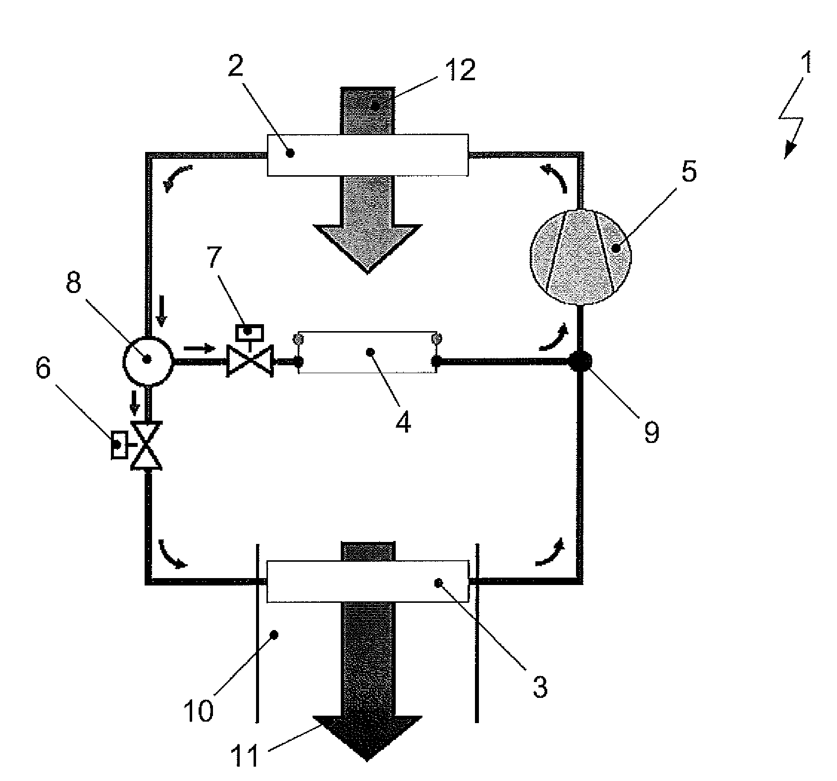
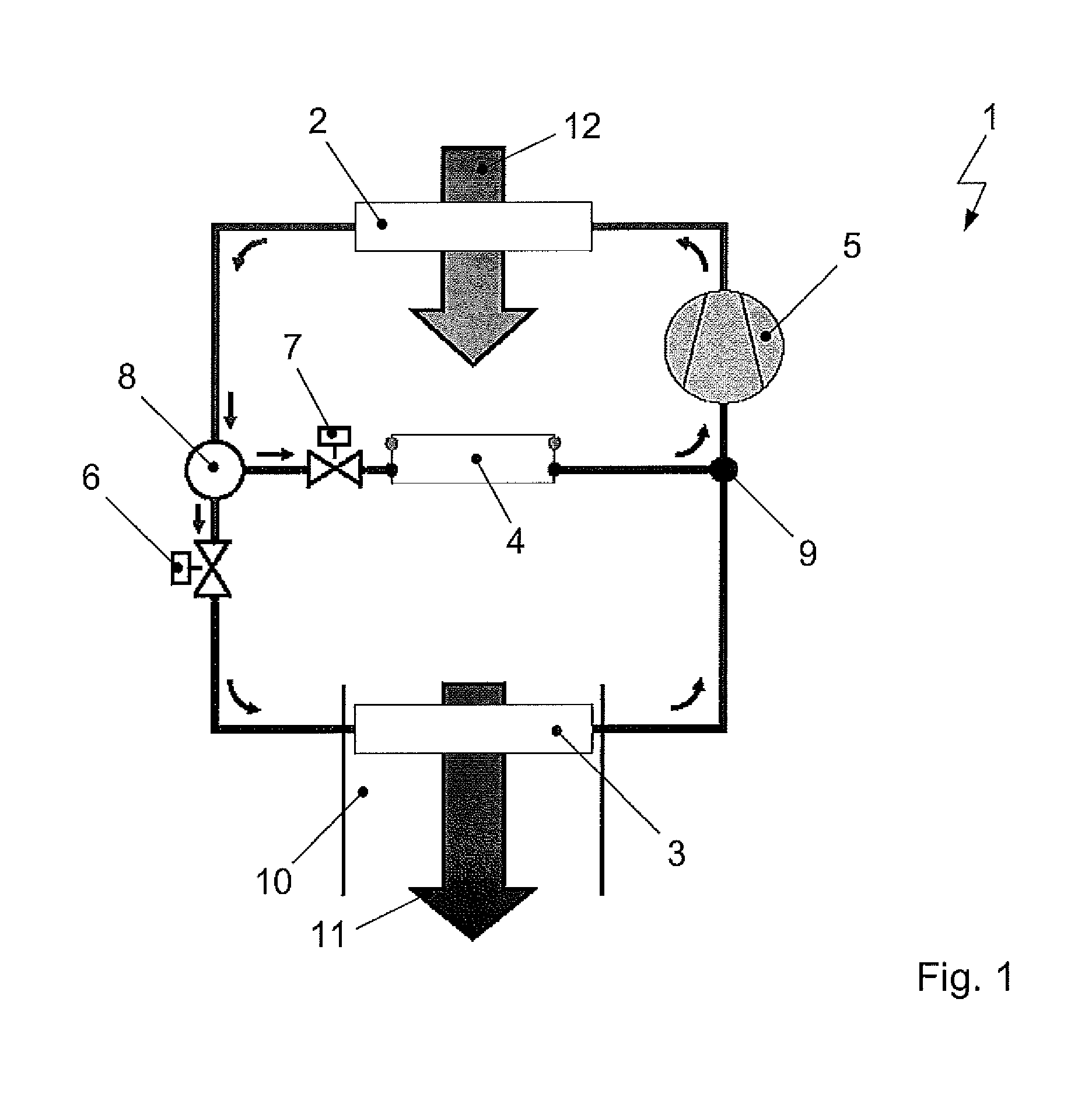
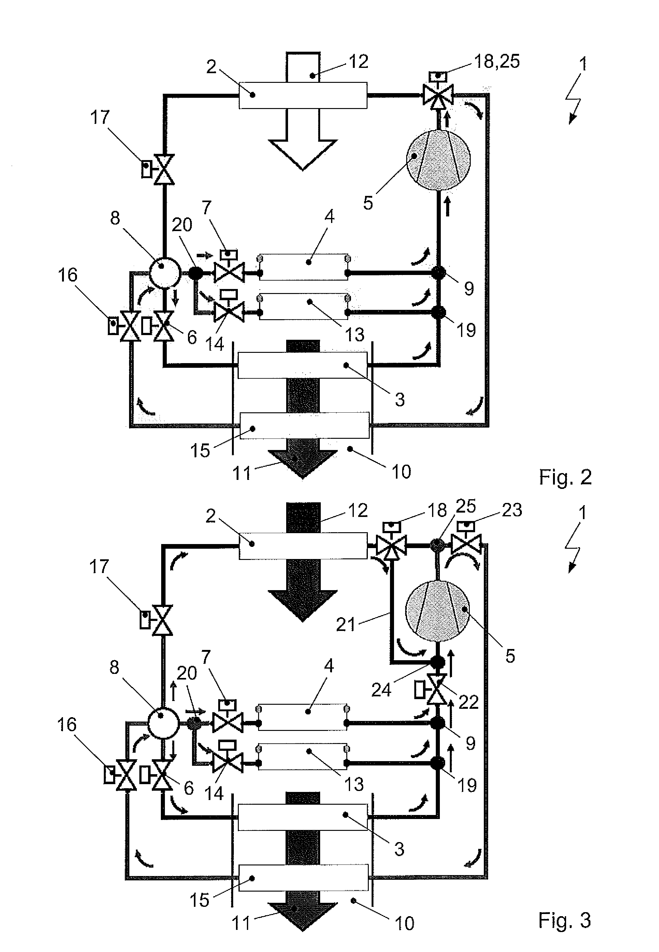
[0057]FIG. 1 shows a refrigerant circuit 1 as primary circuit with, in the direction of flow of the refrigerant, a compressor 5, a condenser 2 for direct heat transmission from the refrigerant to the ambient air 12, a collector 8, a first expansion valve 6 and an evaporator 3 for directly supplying heat from the fresh air to be conditioned for the vehicle interior to the refrigerant. In the direction of flow of the refrigerant between the connection point 8 established as collector 8 and an entering point 9 a further evaporator 4 with upstream expansi...


PUM


Abstract

The invention relates to a refrigerant circuit and a process for operation of the refrigerant circuit of an HVAC system of a vehicle, particularly an electric or hybrid vehicle. The refrigerant circuit includes a primary circuit with a compressor, a heat exchanger for heat transmission between the refrigerant and the environment, a collector, a first expansion member, a heat exchanger for supply of heat from the fresh air to be conditioned of the vehicle interior to the refrigerant and a heat exchanger arranged switched in parallel to the heat exchanger. Further, the refrigerant circuit is provided with a secondary train that extends starting from a tapping point positioned between the compressor and the heat exchanger up to a connection point and is provided with a heat exchanger for heat transmission from the refrigerant to the fresh air to be conditioned for the vehicle interior, and a subsequent control valve.

Description

CROSS-REFERENCE TO RELATED APPLICATION[0001]The present application claims priority to German Patent Application Serial No. DE 10 2010 042 127.8 filed Oct. 7, 2010, the entire disclosure of which is hereby incorporated herein by reference.FIELD OF INVENTION[0002]The invention relates to a refrigerant circuit of an HVAC system of a motor vehicle, particularly an electric or hybrid vehicle, the refrigerant circuit configured to utilize several heat sources and several heat sinks. Further, the invention relates to a process for operating the refrigerant circuit.BACKGROUND OF THE INVENTION[0003]The trend towards high-efficiency, environment-friendly drive systems for motor vehicles means that sufficient waste heat for heating the vehicle interior is no longer available. Compared to vehicle engines, particularly, the drive train of an electric vehicle works much more efficiently. Due to less waste heat and the lower temperature level of the refrigerant circuit that cools the drive train,...

Claims


Application Information

Patent Timeline
IPC IPC(8): F25B29/00
CPCB60H1/00278B60H2001/00307B60H1/323B60H1/143F25B2400/16F25B5/02F25B41/20F25B41/24F25B43/006F25B5/00B60H1/00914
Inventor GRAAF, MARCWIESCHOLLEK, FLORIANREBINGER, CHRISTIANSCHROEDER, DIRK
Owner AUDI AG
Learn More