Limb protection device

a technology for protecting devices and limbs, applied in medical science, non-surgical orthopedic devices, diagnostics, etc., can solve problems such as low limbs, risk of injury, and limb's constituent structures, and achieve the effects of limiting the overall stretch (strain), reducing the risk of injury, and significant passive elastic properties

Active Publication Date: 2012-04-12
HORSEPOWER TECHNOLOGIES INC
View PDF3 Cites 16 Cited by
  • Summary
  • Abstract
  • Description
  • Claims
  • Application Information

AI Technical Summary

Benefits of technology

[0053]Collectively, the SDFT, DDFT and SL are substantially modified muscles, possessing short muscle fibers, a pennate structure (that is, comprising a muscle in which fibers extend obliquely from either side of a central tendon) and significant passive elastic properties. The SL, an evolutionary modification of the interosseus muscle, is completely fibrous with only remnants of muscle fibers to be found. The superficial digital flexor muscle (proximal to but contiguous with the SDFT) is also almost completely fibrous in the hind limb and in the forelimb has short muscle fibers of 2-6 mm length. These are primarily ‘slow’ muscle fibers best suited to supportive rather than propulsive functions by means of constant or extended length activity. The deep digital flexor muscle has three heads or muscle compartments (humeral, radial and ulnar) composed of varying numbers of short, intermediate, and long muscle fibers. It c

Problems solved by technology

The horse's large body size, slender limb structure and occasional need for high speed or rapid acceleration expose the lower limbs, in particular, to risk of injury, either from a single traumatic event such as blunt force trauma or a mis-step of the hoof, or from accumulated micro-damage sustained, for example, during repeated loading of the limb during race training.
Injury arising from a single incident can affect any of the limb's constituent structures, although the more distal (lower limb) components are generally at greater risk by virtue of their proximity to the ground and ground obstructions.
In particular, the fetlock joint, at which the cannon bone meets the pastern bone, is extremely vulnerable to injury, often with catastrophic results.
This higher load may lead to injury, especially if it occurs repetitively.
Once sustained, injury—be it to bone or soft tissue—requires substantial periods of complete rest or much reduced exercise before the animal can return to normal activity, and in some cases the recovery is never complete.
Man's competitive use of horses—which frequently exceeds ‘normal activity’—places additional and frequently unreasonable demands on the healing tissues.
As a result, the healing process can be exacerbated and the injury will fail to fully resolve, causing a chronic and sometimes life-long limitation of use.
Additionally, while bone is unusual in being able to completely heal itself, soft tissues generally heal with some degree of scar formation which results in added compromise of ambulatory ability, mediated, for example, by pain or adhesions.
Scar tissue (unspecialized fibrous tissue in an orientation that is mechanically inferior and/or predisposed to forming adhesions to adjacent structures) is also invariably less strong than undamaged tissue, placing the injured tissue(s) at risk of re-injury.
The situation is complicated by an incomplete understanding of lower limb mechanics, sometimes resulting in contradictory data findings or theorems.
None of the prior art devices shown in the patents and applications mentione

Method used


Image

  • Limb protection device
  • Limb protection device
  • Limb protection device

Examples


Embodiment Construction

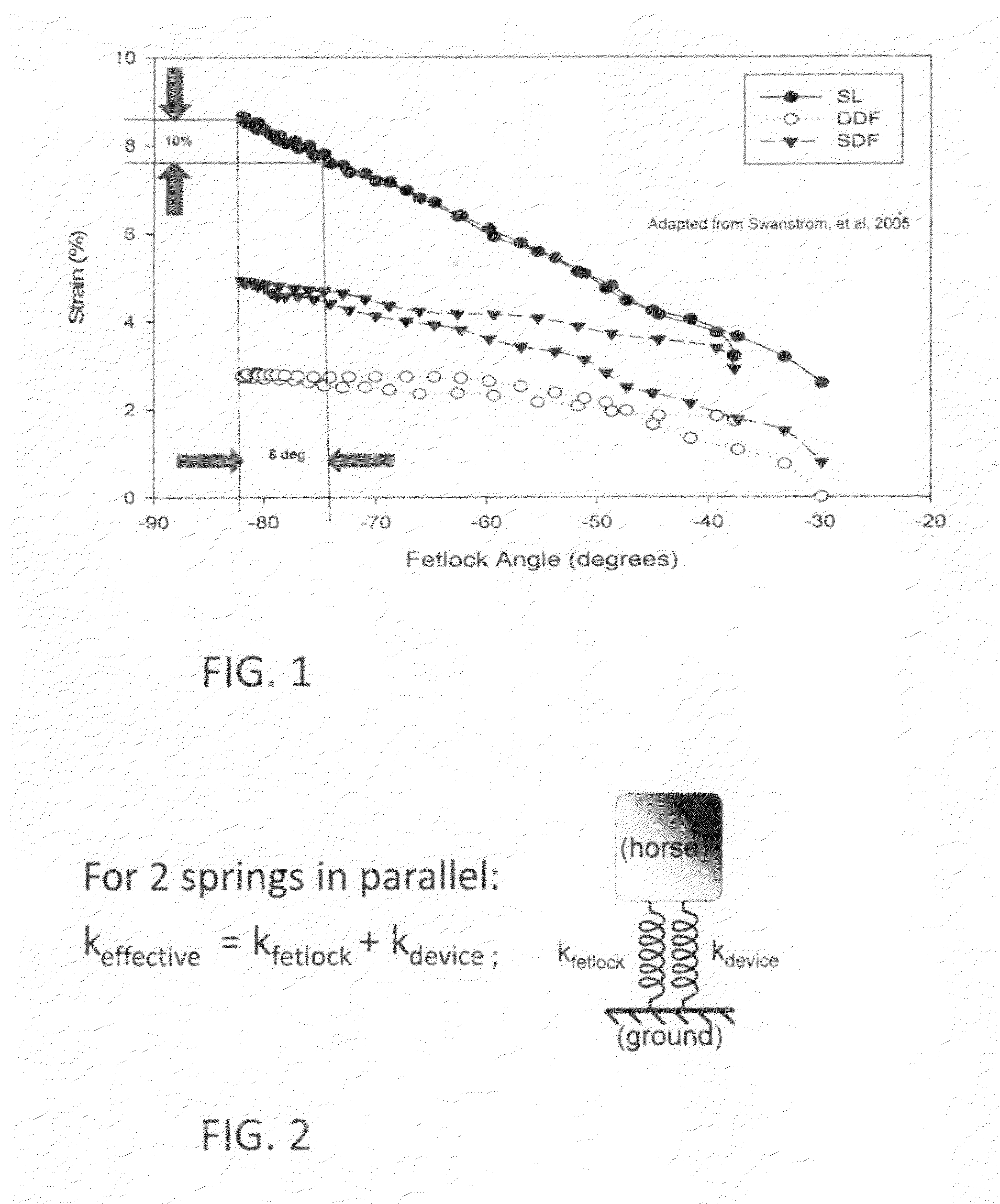
[0093]FIG. 1 shows the strain experienced by the SL, DDF and SDF as the fetlock is flexed during the weight bearing phase of gait. As above, the available data indicates that an eight degree reduction in fetlock angle is required to achieve a ten percent reduction in peak tendon strain. Achieving this eight degree reduction in fetlock extension is accordingly one of the desired design goals of the invention. Along with this reduction in peak fetlock angle, the peak angular velocity will be reduced accordingly. The peak angle will be reduced by adding a parallel load path having the capability of storing and releasing energy, increasing the “springiness” of the fetlock, thereby increasing the overall stiffness of the fetlock joint. Specifically, fetlock stiffness will be increased toward the end of its extension. FIG. 2 shows the approach schematically: The device adds another spring structure in parallel with the SL, DDF and SDF, increasing the effective spring constant experienced ...


PUM


Abstract

A joint-supporting device comprises tensile members extending from above the joint to below it, supplementing the tensile characteristics of the joint's tendons, ligaments, and other structure. The tension members extend between a proximal cuff above the joint to a distal cuff below it, and pass over a pad at the apex of the joint, redirecting the tension members. In order that the cuffs are supported in position so that the tension members can effectively support the joint, they are spaced away from the joint by compression members bearing on proximal and distal bolsters, in turn located positively by the boney structure of the joint.
In order that the structure of the invention not interfere overly with the normal function of the joint, the device employs dilatant materials having the property of varying their hardness upon motion. The dilatant material is disposed so as to limit the relative angular velocity of the members of the joint. The dilatant material can be disposed in pad form, arranged to be compressed by the tensile members as the joint is extended, and/or as the core of a composite tensile member, sheathed in a cover woven of high tensile strength filaments or yarns.

Description

CROSS-REFERENCE TO RELATED APPLICATION[0001]This application claims priority from Provisional Patent Application Ser. No. 61 / 321,212, filed Apr. 6, 2010.FIELD OF THE INVENTION[0002]The invention herein relates to a device to prevent damage to body joints. The invention is described in an embodiment for prevention of equine lower limb injuries during athletic activity, but is not limited thereto.BACKGROUND OF THE INVENTION[0003]Horses are large running mammals, typically weighing 450-500 kg (990-1100 lbs), and sometimes much more. They are capable of rapid acceleration and attaining speeds of 20 ms−1 (44 mph). Evolution and careful breeding have left horses, particularly horses bred for racing and other athletic contests (as opposed, for example, to draft horses) with comparatively slender and fragile legs comprised substantially of long bones articulated by several series of compact muscles, tendons, and ligaments. The latter three soft tissue structures (as opposed to bone and cart...

Claims


Application Information

Patent Timeline
IPC IPC(8): A61F5/00
CPCA61B5/1071A61B5/1121A61B2503/40A61F2005/0172A61F5/0111A61F2005/0167A61D9/00
Inventor PFLASTER, DANIEL SCOTTCRISCO, JOSEPH J.KIRKER-HEAD, CARL A.FIORE, RUSSELL D.DRUMM, WENDY
Owner HORSEPOWER TECHNOLOGIES INC
Why Eureka
Try Eureka