[0033]A further
advantage of a thin film element is that, compared to the other alternatives described herein, they are more robust and less breakable in
field conditions. The film elements are flexible, and when attached to a
solid base of insulating material such as
refractory insulating material, they are near unbreakable, compared to a
quartz tube or a
ceramic tile. The thin film elements are also more resistant to contact to water, which may occur in
field conditions, for example, on off
shore pipe lay-barges. In such conditions, heat shrinkable sleeves are often
water cooled, since soft (still hot) sleeves can get damaged by the
stinger rollers which support the pipe as it is released into the ocean. Cold water used to cool the pipe can splash onto the
heating element as the
heating element is removed or placed on the pipe. In the case of
quartz tubes or
ceramic tiles, this rapid change in temperature can cause
cracking oii, other damage to the
heating element, whereas for the thin film elements, there is less risk of such damage, with the cold water simply
steaming off the element.
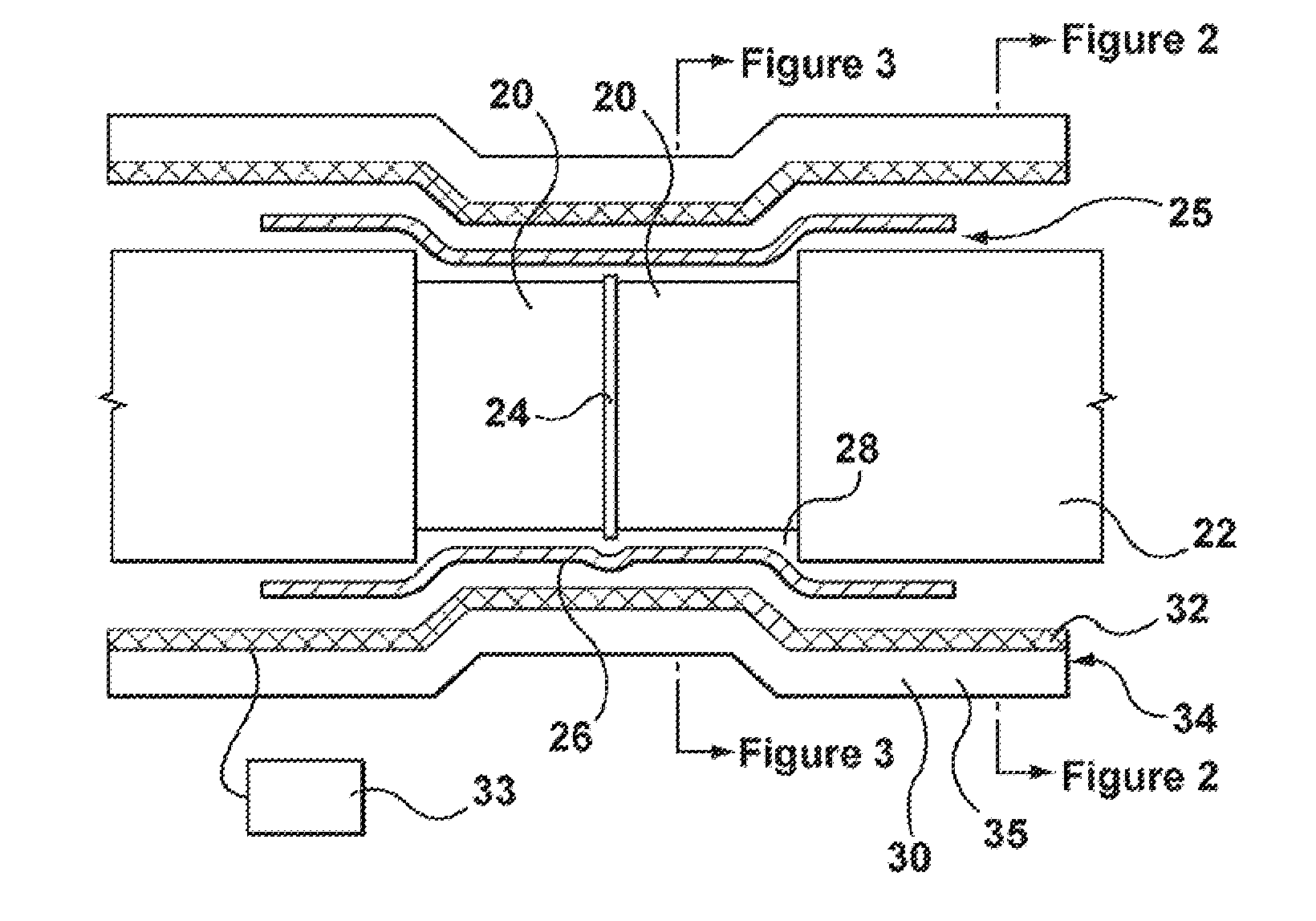
[0034]By using stamped
thin metal strips, different areas can be heated to different temperatures or at different time periods within the heat shrinking process, simply by having separate heating elements applied to different areas of the apparatus, and having each of these separate heating elements controlled individually by the controller. The different heating elements may be individually thermostatically controlled by the controller, and / or may have different heating characteristics (for example, made of different substrates or having a different coil thickness) to enable the variation in heating. With this arrangement, at least in preferred embodiments, the heating of the sleeve can be carefully controlled to shrink down the
middle zone of the sleeve before the end zones, avoiding air
entrapment. Moreover, in certain embodiments, once the
middle zone of the sleeve is shrunk, the end zones can be shrunk simultaneously, providing for fast installation before the mainline coatings cool down below a required preheat temperature. In case of the preheating of a pipe joint, this arrangement also permits heating the areas of bare pipe to a higher heat level than the areas of coated pipe, thus preventing damage to the pipe coating while providing the bare pipe with optimal heat. Though this controlled heating can be done with the other heating elements described, a further
advantage of utilising thin film elements is that the element heats, and cools, much more rapidly. In many cases, the thin film element will cool down with 5-10 seconds of deactivation, and will heat up in a
similar time frame. For example, certain
metallic foil type elements can have a temperature rise of 700 degrees Celsius, in 10 seconds. Others can cool down in as little as 2 seconds. This means that the controller can control the zone changes much more effectively, rapidly, and precisely. It also means that the pipe joint can be heated, or the sleeve can be shrunk, much more rapidly. This rapid cooling of the thin film elements also adds a safety feature when used in the field, such as on an offshore pipe lay-
barge, where
work space is crammed—worker safety is dramatically improved, since the heating elements are much cooler when the apparatus is handled, for example, when the apparatus is clamped to, or removed from, a pipe. In addition, the rapid heating and cooling of the film elements can result in significant time and
energy cost savings, up to 20%.
[0035]The apparatus can also be used before and after application of the heat shrinkable sleeve. For example, the apparatus can be placed around the welded pipe joint, for preheating the welded pipe joint before application of the heat shrinkable sleeve. Once the pipe has been preheated to a desired extent (i.e. after a pre-set temperature or a pre-set time has been reached), the apparatus (including the heating element) can then easily be removed, and the heat shrinkable sleeve can be applied. The apparatus may optionally then be placed around the welded pipe joint again, and heat re-applied, to shrink the heat shrinkable sleeve. This permits a much more consistent and even pre-heating of the pipe joint than previous methods, where, often, different areas of the pipe joint were pre-heated at different times, with
resultant unevenness in cooling before the sleeve was applied.
[0036]The apparatus can also be used to preheat the pipe joint for other coating applications, for example, before the application of a film or tape wrapping, or an
injection moulding of a coating. As would be appreciated, a further
advantage of using the apparatus in certain embodiments is that the entire pipe joint or sections of the pipe joint can be brought to a desired temperature, at the same time, and the apparatus can be quickly removed and the application of coating can be started much more quickly than in more traditional preheating methods.

