
High performance fluorescent lamp

a fluorescent lamp, high-performance technology, applied in the direction of discharge tubes, discharge tubes luminescnet screens, low-pressure discharge lamps, etc., can solve the problems of amalgam, high cost of lamp for higher operation temperature, and corresponding increase in vapor pressure, so as to prevent any unwanted movement of amalgam

Inactive Publication Date: 2012-04-19
KONG QIN
View PDF4 Cites 6 Cited by
  • Summary
  • Abstract
  • Description
  • Claims
  • Application Information

AI Technical Summary

Benefits of technology

[0012]Another advantage of the invention is to provide a high performance fluorescent lamp, wherein the lamp can be operated under different ambient temperature or different wattage of the lamp with the same type of amalgam by controlling a distance between the amalgam and the respective filament of the electrode. In other words, there are different techniques to control the temperature at the location of the amalgam, wherein such techniques can be used individually or combined to achieve the right temperature at the amalgam location.
[0013]Another advantage of the invention is to provide a high performance fluorescent lamp, wherein the amalgam is retained and blocked within the tail pipe by the narrow opening thereof to retain a fixed position and to prevent any unwanted movement of the amalgam disposed in the tail pipe.
[0014]Another advantage of the invention is to provide a high performance fluorescent lamp, which has adjusted Voltage-Current characteristic and improved light efficient.
[0015]Another advantage of the invention is to provide a high performance fluorescent lamp, which can produce an ideal wider range of wavelength of visible light similar to sunlight spectrum.
[0016]Another advantage of the invention is to provide a high performance fluorescent lamp, wherein the Xenon gas of the inert gas is further added for increasing the lamp voltage, so as to enhance the efficiency of the fluorescent lamp.

Problems solved by technology

When the ambient temperature increased, the mercury vapor pressure is correspondingly increased and the self-absorption in the vapor reduces the yield of UV and visible light.
Amalgam, to be used in the lamp for higher operation temperature is expensive and needed an auxiliary amalgam.
An expensive high temperature amalgam has to be used if the lamp needs to be operated at higher ambient temperature.
Therefore, such lamp is extremely expensive and is difficult to manufacture.
However, human being can only see portion of sunlight.
It will generate more heat and lower the efficiency of the lamp.

Method used


Image

  • High performance fluorescent lamp
  • High performance fluorescent lamp
  • High performance fluorescent lamp

Examples


Embodiment Construction

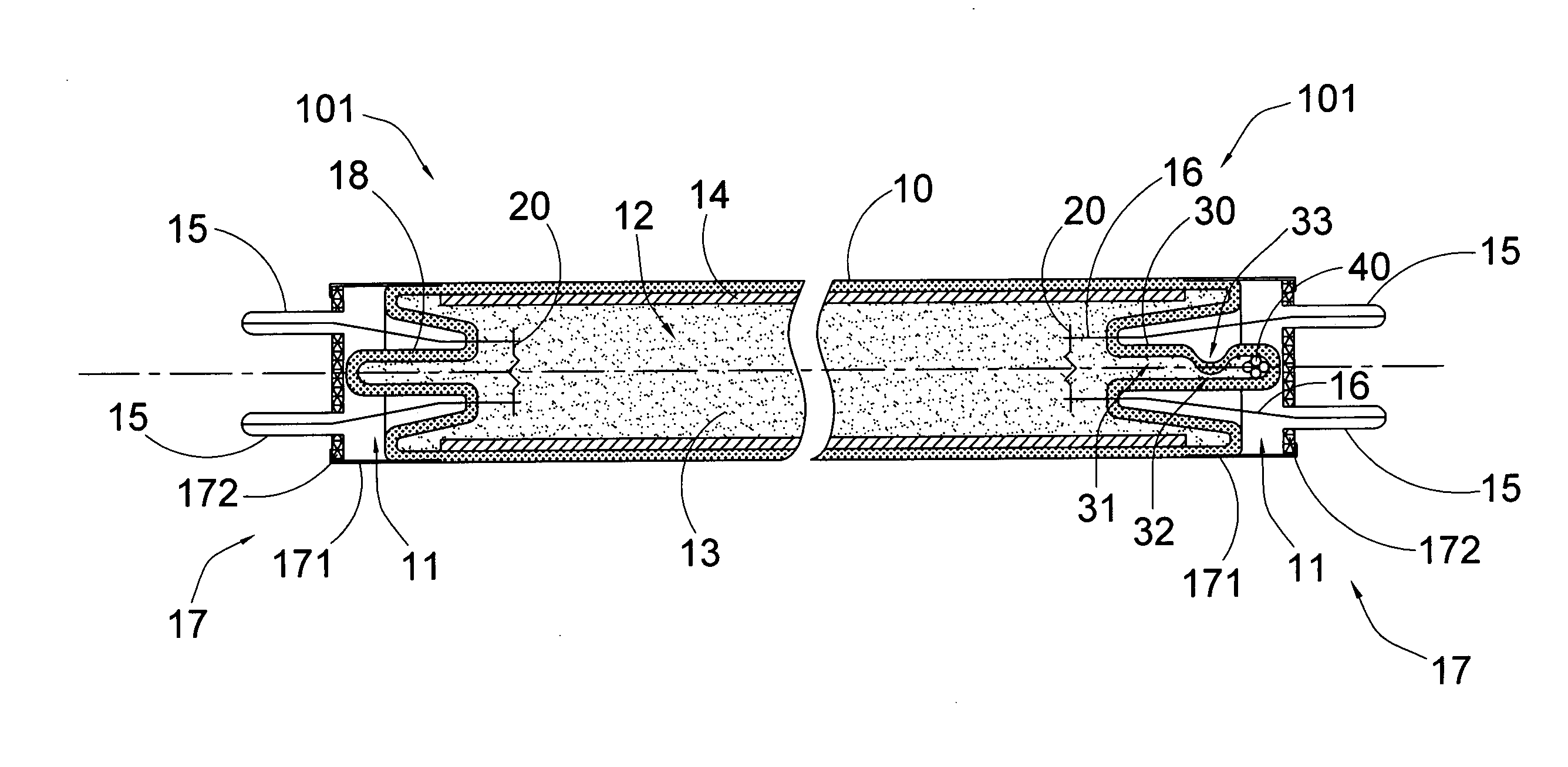
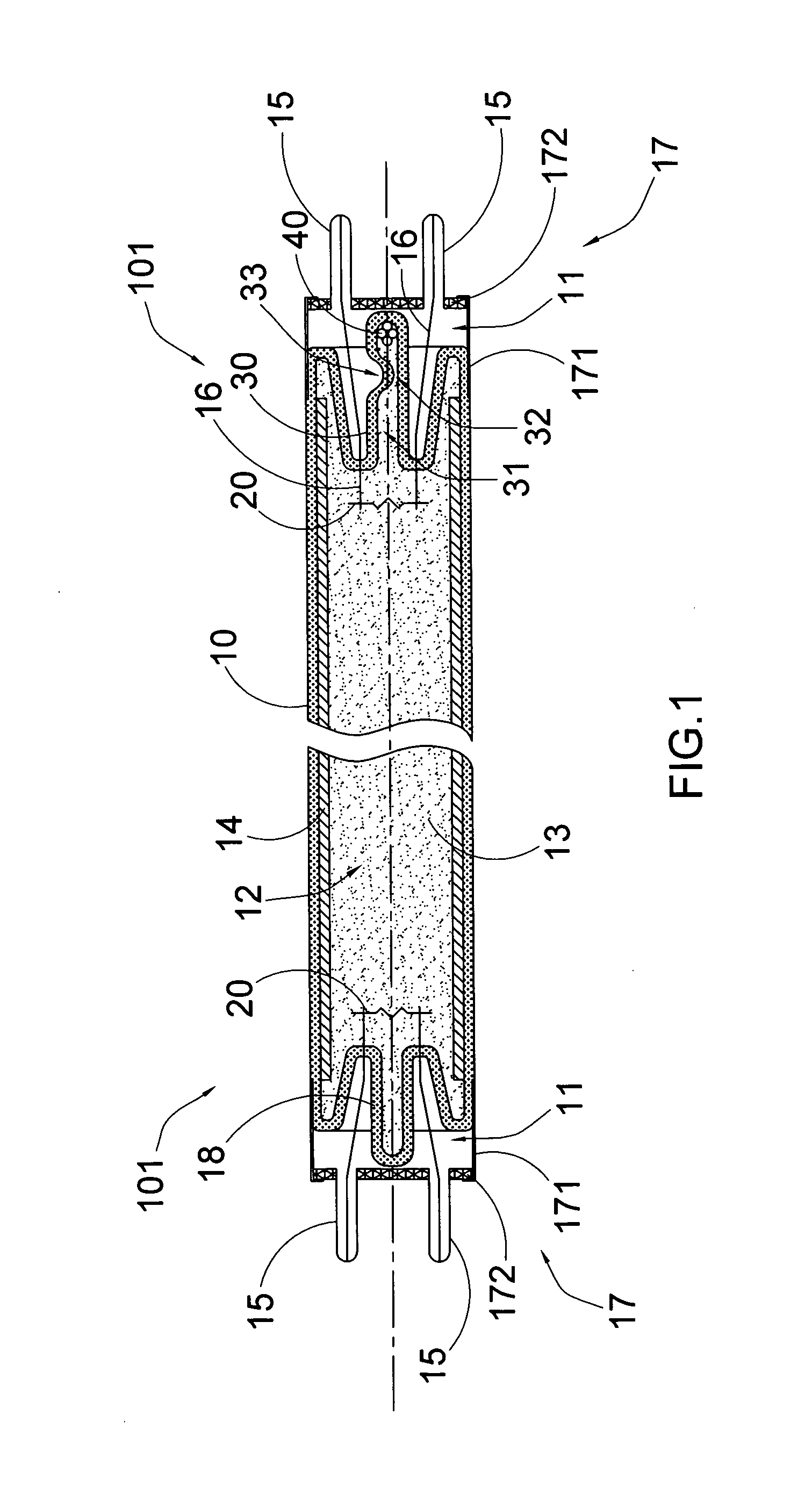
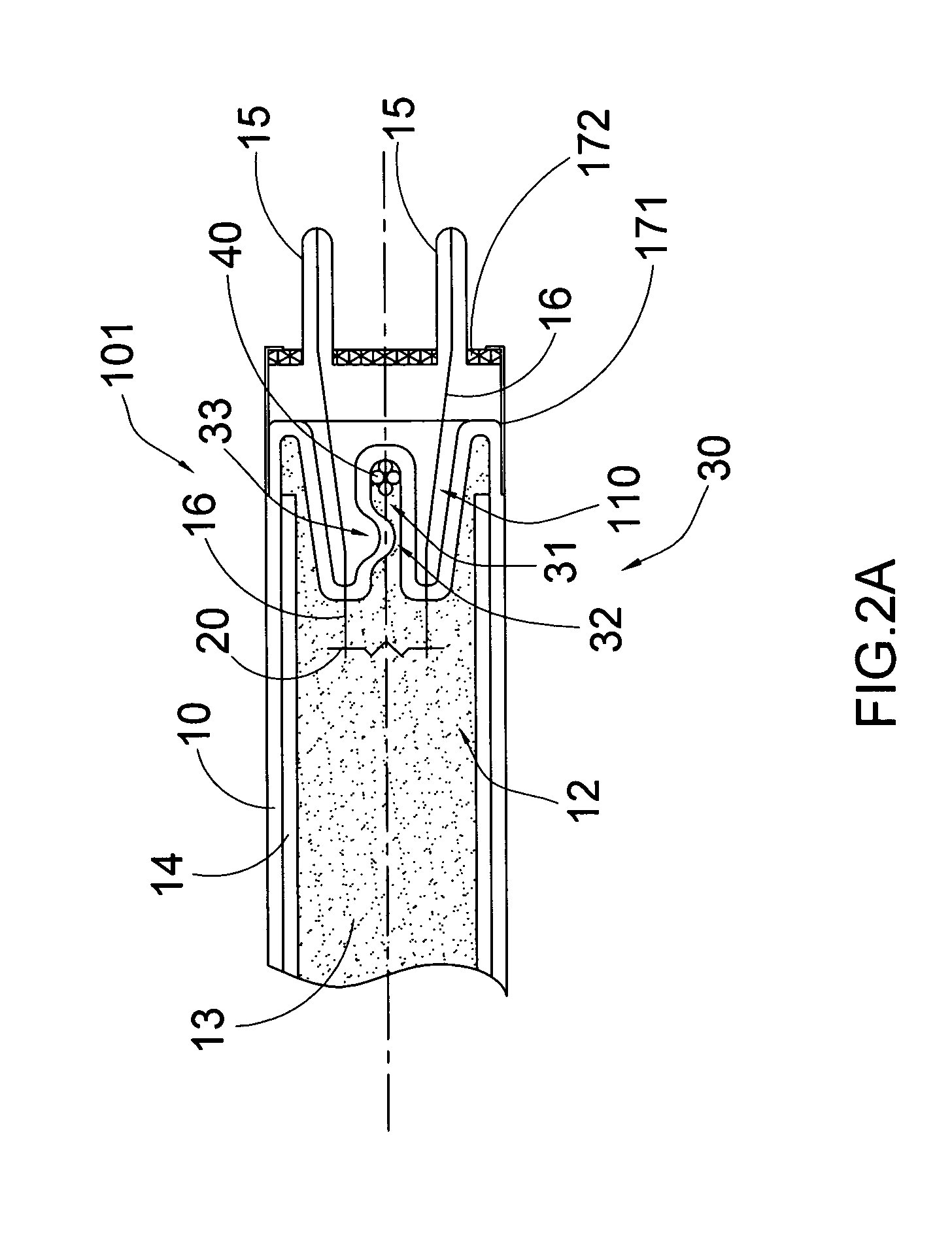
[0034]Referring to FIGS. 1 to 4 of the drawings, a high performance fluorescent lamp according to a preferred embodiment of the present invention is illustrated, wherein said fluorescent lamp comprises an air-tight glass envelop 10 having two sealed ends 11 and a light cavity 12 formed between the sealed ends 11 and two electrodes 101 provided at the two sealed ends 11 of the glass envelop 10 within the light cavity 12. Each electrode 101 includes a filament 20 and two or more contact terminals 15, and support wires 16 which support the filament 20 in position and extended from the filament 20 to the contact terminals 15 respectively for power supply.

[0035]Accordingly, the light cavity 12 of the glass envelop 10 is filled with inert gas 13 and coated with a phosphor powder 14 at an inner wall of the light cavity 12 of the air-tight glass envelop 10. A low pressure metal vapor, preferably Mercury vapor, is also filled within the light cavity 12 of the glass envelop 10 to mix with the...


PUM


Abstract

A high performance fluorescent lamp includes an air-tight glass envelop having sealed ends and a light cavity filled with inert gas and coated with a phosphor powder at an inner wall of the glass envelop. Two filaments are sealed at the sealed ends of the glass envelop respectively. A channel is formed at one of the sealed ends of the glass envelop at a location communicating with the light cavity of the glass envelop. An amalgam is retained within the channel at a position forming a preset distance between the respective filament and the amalgam. Therefore, the fluorescent lamp can be operated under different ambient temperature or different wattage of the fluorescent lamp with the similar type of amalgam by controlling a distance between the amalgam and the respective filament.

Description

BACKGROUND OF THE PRESENT INVENTION[0001]1. Field of Invention[0002]The present invention relates to a fluorescent lamp, and more particularly to a high performance fluorescent lamp which has low manufacturing cost and simple structural configuration for manufacture.[0003]2. Description of Related Arts[0004]The fluorescent lamp is basically a low pressure mercury discharge lamp. A conventional fluorescent generally comprises an air-tight tubular casing coated with fluorescent powder or phosphors powder at an inner wall thereof and filled with lower pressure mercury vapor and inert gases, and two electrodes at two ends of the tubular casing. When the electrodes are connected to a power source and electrified, the voltage between the two electrodes will break down the inert gases and the electron can go through between the electrodes. The mercury atoms are excited by the electrons for emitting Ultraviolet (UV) light. Then, the coating of fluorescent powder or phosphors powder will con...

Claims


Application Information

Patent Timeline
Patent Type & Authority Applications(United States)
IPC IPC(8): H01J1/62
CPCH01J61/72H01J61/28
Inventor KONG, QIN
Owner KONG QIN
Learn More