
Common mode filter

a filter and common mode technology, applied in the field of common mode filters, can solve the problems of deteriorating the noise resistance property, increasing the impedance of two conducting wires, and insufficient attenuation function of common mode signals such as external noise, so as to achieve excellent transmission, easy to obtain planar structure, and sufficiently attenuation

Inactive Publication Date: 2012-04-26
ELMEC
View PDF1 Cites 14 Cited by
  • Summary
  • Abstract
  • Description
  • Claims
  • Application Information

AI Technical Summary

Benefits of technology

[0037]According to the common mode filter of claim 1 of the present invention with this structure, the common mode signal is cut off and absorbed by the distributed constant-type differential transmission line formed by the conductive line and the first floating ground, and the first passive two terminal circuit connected between the first floating ground and the external ground potential. Therefore, the ultrahigh speed differential signal can be excellently transmitted and the common mode signal can be sufficiently attenuated in a microstrip line structure.
[0038]According to the common mode filter of claim 2 of the present invention, the first floating ground is divided into a plurality of parts in the length direction of the conductor lines, and the first passive two terminal circuit is connected between these divided floating grounds and the external ground. Therefore, various attenuation characteristics for cutting off and absorbing the common mode signal can be obtained in the microstrip line structure.
[0039]According to the common mode filter of claim 3 of the present invention, there is provided the first common mode ground connected to the external ground with the first passive two terminal circuit disposed between them, with the first passive two terminal circuit connected between respective end portions of the first floating ground and the first common ground. Therefore, in addition to the aforementioned effect, a planar structure can be easily obtained and a simple structure can be easily obtained.
[0040]According to the common mode filter of claim 4 of the present invention, the first common ground is disposed at the position opposed to the first floating ground, and the first passive two terminal circuit is connected between respective end portions at the opposed position. Therefore, similarly the planar structure can be easily obtained, and also the simple structure can be easily obtained.
[0041]According to the common mode filter of claim 5 of the present invention, the divided first floating grounds are formed so that the first passive two terminal circuit is connected between all or apart of the adjacent divided floating grounds. Accordingly, the common mode signal takes a route of returning to the common ground via the adjacent floating grounds, and further more passive two terminal circuits are connected in series on the route. Therefore, various attenuation characteristics for cutting off and absorbing the common mode signal can be efficiently and easily obtained.
[0042]According to the common mode filter of claim 6 of the present invention, there is provided a second floating ground separated from the external ground potential, and formed to face the conductor lines with a second dielectric layer interposed between them, and configured to form a distributed constant-type differential transmission line. Therefore, the attenuation characteristic for sufficiently attenuating the common mode signal can be obtained in the strip line structure.

Problems solved by technology

In the ultrahigh speed serial transmission, small voltage amplitude is required for shortening a rise time, thus deteriorating a noise resistance property.
However, in the differential transmission system, a function of attenuating the common mode signal such as the external noise is insufficient.
Meanwhile, the common mode signal flows through two conducting wires in the in-phase state, and all magnetic fluxes generated in a magnetic body are totaled, to thereby increase the impedance of two conducting wires and hardly allow the common mode signal to pass.

Method used


Image

  • Common mode filter
  • Common mode filter
  • Common mode filter

Examples


Embodiment Construction

[0077]Preferred embodiments of the present invention will be described hereafter, with reference to the drawings.

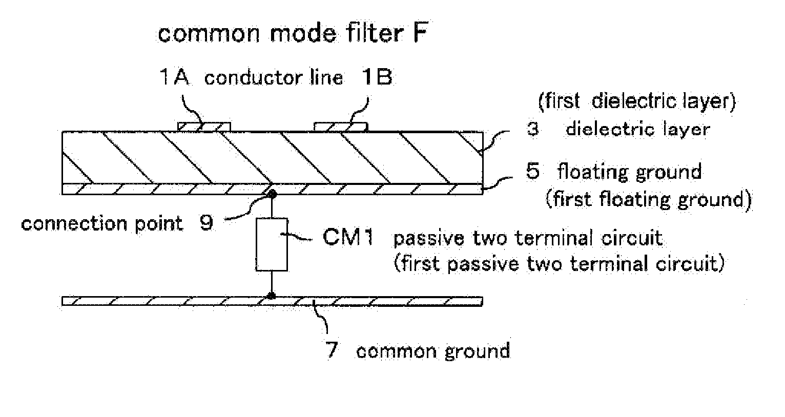
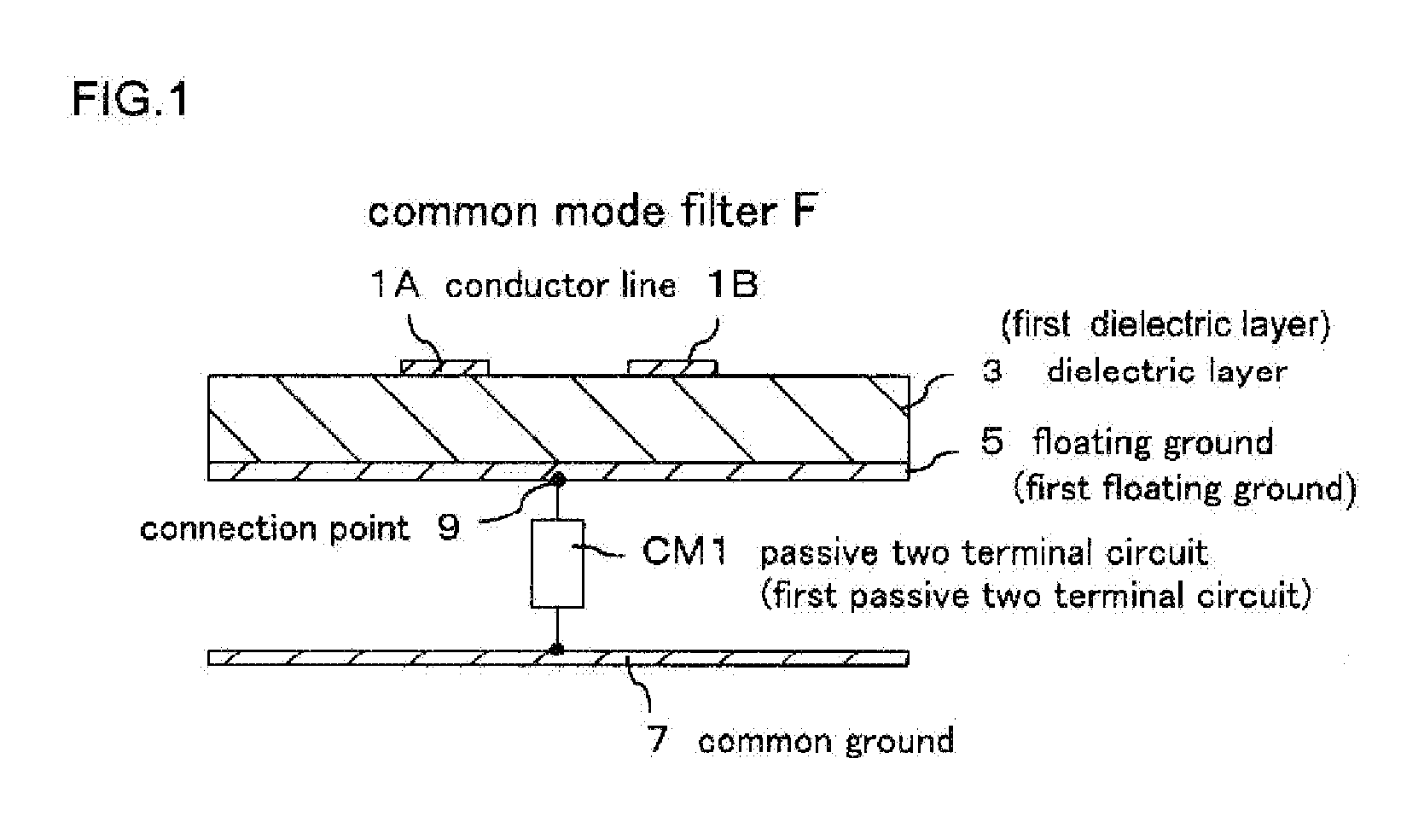
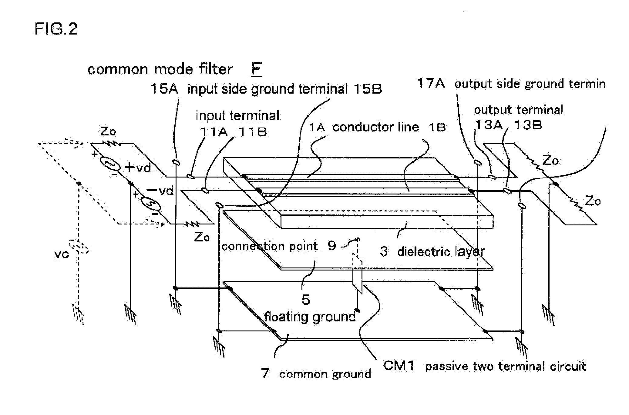
[0078]FIG. 1 is a schematic cross-sectional view showing a basic structure of a common mode filter F according to the present invention, and FIG. 2 is an exploded perspective view showing a form of the common mode filter F in perspective. An external circuit is also included in FIG. 2.

[0079]In FIG. 1 and FIG. 2, a pair of film-like conductor lines 1A and 1B are formed on one side (upper surface in the figure) of a square, for example, rectangular thin plate-like dielectric layer 3, at an equal interval, separated from each other, and in parallel with each other.

[0080]A conductive floating ground 5 is formed on an entire surface of the other side (lower surface in the figure) of the dielectric layer 3, in such a manner as facing the conductor lines 1A and 1B, thus forming a micro strip distributed constant type differential transmission line. A function of the floating gro...


PUM


Abstract

To pass an ultrahigh speed differential signal and sufficiently attenuate a common mode signal on an ultrahigh speed differential transmission line. A pair of conductor lines 1A and 1B are formed on one side of a dielectric layer 3 in parallel to each other. A floating ground 5 is formed on the other side of the dielectric layer 3 so as to face the conductor lines 1A and 1B. The floating ground 5 is not connected to an external common ground 7 and is formed independently. A passive two terminal circuit CM1 composed of passive circuit elements is connected between a connection point 9 between the floating ground 5 and a common ground 7.

Description

TECHNICAL FIELD[0001]The present invention relates to a common mode filter, and particularly to a new common mode filter capable of securing a transmission of an ultrahigh speed differential signal which is propagated through an ultrahigh speed differential line, and attenuating a common mode signal.DESCRIPTION OF RELATED ART[0002]In recent years, high definition video contents such as “HDTV: high definition television” and “Blu-ray Disc” are widespread. In order to transmit an enormous amount of digital data that supports such contents at a high speed, an ultrahigh speed serial transmission has been used.[0003]In the ultrahigh speed serial transmission, small voltage amplitude is required for shortening a rise time, thus deteriorating a noise resistance property. Therefore, in order to improve the noise resistance property, a differential transmission system generally used.[0004]This differential transmission system is capable of ensuring a smaller amplitude for a higher transmissi...

Claims


Application Information

Patent Timeline
IPC IPC(8): H01P1/203
CPCH01P3/026H01P1/20
Inventor KAMEYA, MASAAKI
Owner ELMEC
Learn More