Method for strengthening ceramicization of floated crystallizable glass
a technology of floated crystal glass and ceramics, which is applied in the field of ceramicizing floated glass, can solve the problems of cracks in the surface, reduced and strong crack formation in the surface, so as to reduce impact strength and bending tensile strength
- Summary
- Abstract
- Description
- Claims
- Application Information
AI Technical Summary
Benefits of technology
Problems solved by technology
Method used
Image
Examples
example 1
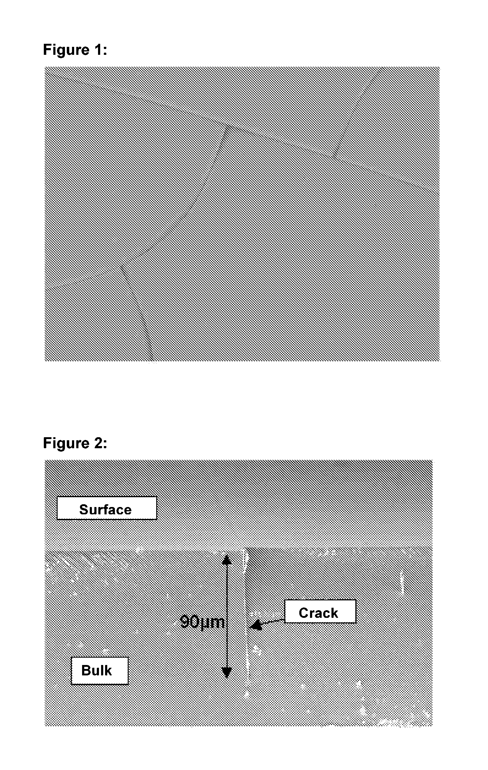
[0038]This example was conducted with a glass melt of the composition (in % by weight on oxide basis): 66.1 SiO2, 22.4 Al2O3, 4.1 Li2O, 0.6 Na2O, 0.2 K2O, 1.0 MgO, 1.3 P2O3, 1.5 TiO2, 2.0 ZrO2, 0.4 SnO2, 0.3 ZrO. The glass was melted in a melting tank in common oxygen containing atmosphere with raw materials which are common in glass industry and transferred into the floating part with reducing atmosphere over a fluting and cast onto the floating bath. The temperatures of the glass were about 1200° C. at the end of the restrictor tiles.
[0039]At the end of the floating bath the glass was removed nearly above the transformation temperature and stress-relieved in a cooling device.
[0040]In a second step the thus obtained glass was converted into a glass ceramic by tempering in a kiln. In a first tempering step the starting glass was subjected to a heating phase, in this example of up to 735° C. The article was held in the nucleation phase for 45 minutes. In a further heating phase the a...
example 2
[0043]Example 1 was repeated with the difference that during the ceramicization step prior to reaching the transformation temperature, here in this example starting from 600° C., and till the end of the first crystallization step, here in this example 850° C., an absolute humidity of at least 6% by volume prevailed in the furnace atmosphere. The glass ceramic thus obtained did not show any surface cracks. The bending tensile strengths measured were between 51 and 68 MPa.
example 3
[0044]Example 1 was repeated with the difference, that the ceramicization step was conducted under a forming gas atmosphere having a fraction of hydrogen of 10%. The obtained glass ceramic did also not show any surface cracks.
[0045]The following tables show that the fraction by volume of water in the ceramicization atmosphere has a strong influence on the bending tensile strength of the respective ceramicized float glass (table 1) and that the same also applies to the fraction of volume of hydrogen (table 2).
TABLE 1Depth of Li depletion, tendency to the formation of cracks and bending tensilestrength at different atmosphere humidities during the ceramicization step.Upper side of float glassLower side of float glassBendingBendingAbsolute humidityLi depletionFormationtensileLi depletionFormationtensilein [% by volume]in μmof cracksstrength1in μmof cracksstrength10.2% 2.46 (± 0.12)strong271.80 (± 0.02)strong353%2.04 (± 0.10)strong261.36 (± 0.07)present376%0.78 (± 0.06)no510.75 (± 0.06...
PUM
| Property | Measurement | Unit |
|---|---|---|
| Percent by volume | aaaaa | aaaaa |
| Percent by volume | aaaaa | aaaaa |
| Percent by volume | aaaaa | aaaaa |
Abstract
Description
Claims
Application Information
 - R&D
- Intellectual Property
- Life Sciences
- Materials
- Tech Scout
- Unparalleled Data Quality
- Higher Quality Content
- 60% Fewer Hallucinations
Browse by: Latest US Patents, China's latest patents, Technical Efficacy Thesaurus, Application Domain, Technology Topic, Popular Technical Reports.
© 2025 PatSnap. All rights reserved.Legal|Privacy policy|Modern Slavery Act Transparency Statement|Sitemap|About US| Contact US: help@patsnap.com

