Introducer Assembly and Dilator Tip Therefor

a technology of dilator tip and inserter, which is applied in the direction of functional valve types, operating means/releasing devices of valves, catheters, etc., can solve the problems of inability to position the device close enough, limit the position in which the device can be positioned, and inability to be positioned close enough, so as to improve the method of implantable medical devices

Inactive Publication Date: 2012-05-03
COOK MEDICAL TECH LLC
View PDF2 Cites 13 Cited by
  • Summary
  • Abstract
  • Description
  • Claims
  • Application Information

AI Technical Summary

Benefits of technology

[0005]The present invention seeks to provide an improved introducer assembly and an improved method of deploying implantable medical devices.

Problems solved by technology

There are some circumstances, however, where it is disadvantageous to have the dilator tip positioned beyond the treatment site, particularly when this results in the dilator tip being moved into a delicate part of a patient's lumen or against or into an organ or other delicate site.
A particular issue arises when it is desired to place a medical device very close to the heart, where there is a compromise between the proximity to the heart to which a device can be placed and having to pass the dilator tip beyond the aortic valve.
In some cases it might not be disadvantageous to push the dilator tip through the heart valve but there are many instances where this is not is desirable.
A problem with current introducer systems is that if the dilator tip is to be kept clear of the aortic valve, there is a limit to the position in which the device can be positioned, in light of the length of the dilator tip.
Thus, either the device cannot be positioned close enough to the aortic valve or the dilator tip has to breach the valve.

Method used


Image

  • Introducer Assembly and Dilator Tip Therefor
  • Introducer Assembly and Dilator Tip Therefor
  • Introducer Assembly and Dilator Tip Therefor

Examples


Embodiment Construction

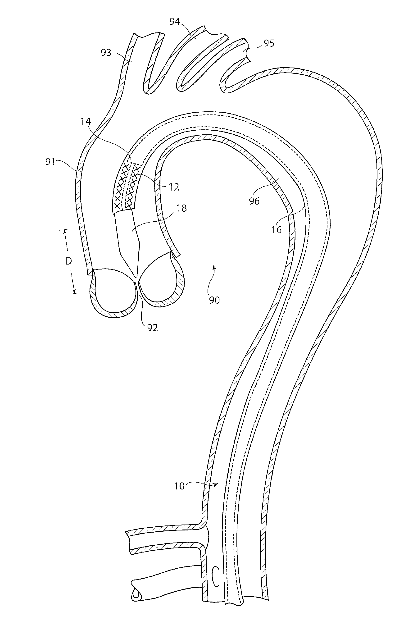
[0029]Referring to FIG. 1, there is shown in cross-section an example of a thoracic aorta. It will be seen that the thoracic aorta 90 comprises an ascending aorta 91 which receives blood from the heart through an aortic valve 92. At the upper end of the ascending aorta there are branches for the great vessels, the innominate artery 93, the left common carotid artery 94 and the left subclavian artery 95. The aorta after these great vessels is referred to as the descending aorta 96.

[0030]Located within the aorta there is shown a prior art introducer assembly 10, which typically passes into the patient's vasculature through the femoral artery (not shown) and in this example through the aortic arch to a location just proximate the aortic valve 92. The introducer assembly 10 carries an implantable medical device 12, for instance a stent graft, within a holding sheath 16. The assembly typically includes a pusher member 14 for pushing the device 12 to the deployment site or otherwise for h...


PUM


Abstract

An introducer assembly (20) for the deployment of an implantable medical device (12) such as a stent, stent graft or other medical device, includes a dilator tip (22) which is able to be compressed radially so as to be withdrawn into the introducer assembly (20) so as to position the implantable medical device (12) at the distal most end of the introducer assembly once the dilator tip has been withdrawn. This enables the implantable medical device (12) to be positioned much closer to both parts of a patient's anatomy, for instance much closer to an aortic valve (92). In the preferred embodiment the dilator tip (22) includes an inflatable and deflatable balloon element (28) which is able to be withdrawn into the assembly while the implantable medical device (12) remains in its constrained position in the introducer assembly (20).

Description

TECHNICAL FIELD[0001]The present invention relates to an introducer assembly and to a method of deploying an implantable medical device.BACKGROUND OF THE INVENTION[0002]Introducer assemblies are in common use for deploying endoluminally a variety of implantable medical devices. These assemblies are generally of an “over the wire” type, in which a guide wire is first passed through the vasculature of a patient up to an often beyond the site at which treatment is to be effected. The guide wire acts to guide the subsequent insertion of the introducer assembly into the patient, which assembly will carry a medical device to be implanted in the patient or otherwise apparatus such as catheters, angioplasty balloons and so on, to the treatment site. The introducer assembly, whether or not of the over the wire type, will generally include a sheath or catheter of a size able to hold the medical device or other equipment to be introduced, as well as a dilator tip at the distal end of the intro...

Claims


Application Information

Patent Timeline
Patent Type & Authority Applications(United States)
IPC IPC(8): A61M29/02A61F2/966F16K15/14F16K31/26
CPCA61F2/966A61M25/0069A61M25/1002A61M29/02A61M2025/0687A61M2025/1072A61F2/95
Inventor RASMUSSEN, ERIK E.
Owner COOK MEDICAL TECH LLC
Why Eureka
Try Eureka