Moisture Probe and System

a technology of moisture probe and system, applied in the direction of resistance/reactance/impedence, instruments, etc., can solve the problems of no feedback mechanism, serious under-watering of plants, and excessive watering leading to runoff, so as to reduce power dissipation and emissions, and small form factor

a technology of moisture probe and system, applied in the direction of resistance/reactance/impedence, instruments, etc., can solve the problems of no feedback mechanism, serious under-watering of plants, and excessive watering leading to runoff, so as to reduce power dissipation and emissions, and small form factor

US20120126026A1Inactive Publication Date: 2012-05-24SPARKS STEVEN ERNEST

Image

  • Moisture Probe and System
  • Moisture Probe and System
  • Moisture Probe and System

Examples


Embodiment Construction

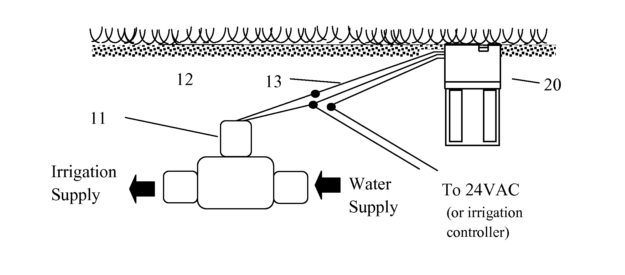
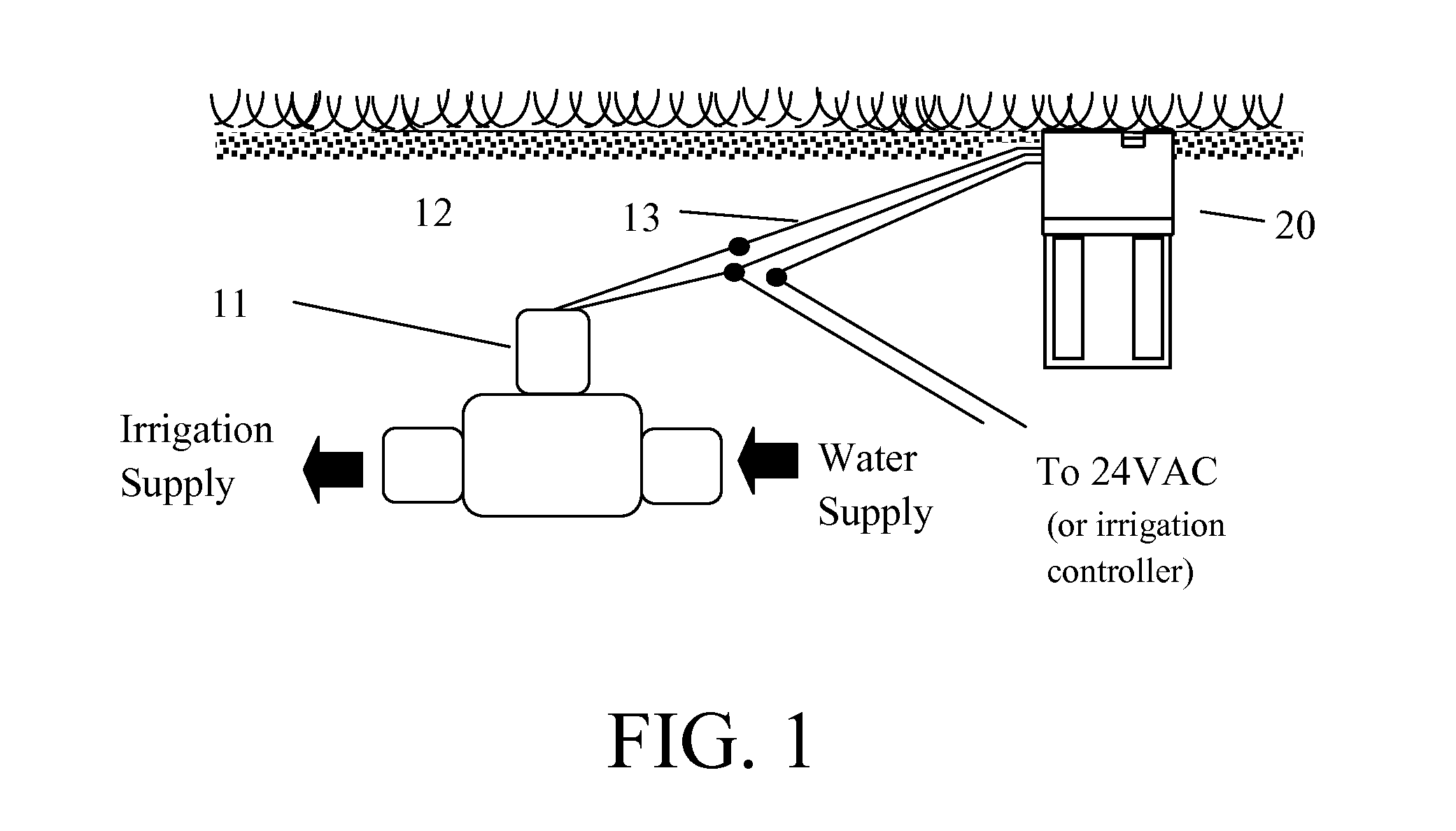
[0027]Referring to FIG. 1 an irrigation system is represented by a water solenoid-valve 11 and present invention 20 buried in soil 12 and is further electrically connected to each other with electrical wiring 13. The moisture probe and system 20, and water solenoid-valve 11 is further connected directly to 24VAC in a preferred embodiment.

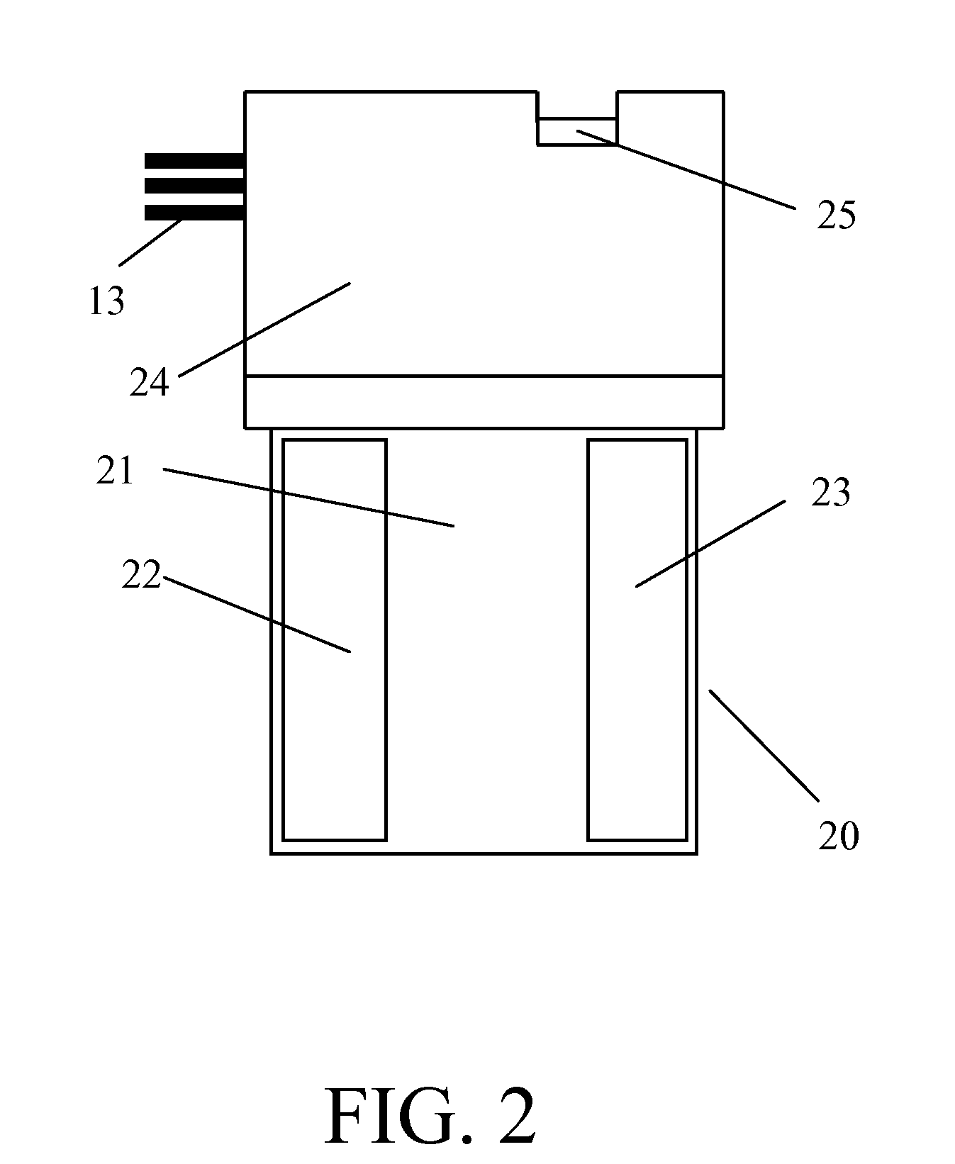
[0028]FIG. 2 illustrates a close-up representative scaling of the moisture probe and system 20 from FIG. 1. There are two primary components to the invention 20, the electronics housed in case 24, and the probe 21. The probe 21 is a substrate containing two conductive plates 22 and 23 that form two plates of a capacitor. This probe assembly 21 is further structurally and electrically connected to the electronics in case 24. The case 24 provides a protective environmental barrier for the electronics. A temperature sensing electrode 25 has been integrated as part of the electronics case 24. The wires 13 enter case 24 to provide power for the invention...


PUM


Abstract

An advanced landscape irrigation control system that integrates a soil moisture probe with a timer-based controller which can be used to directly control a single irrigation zone without need for a separate timer-based controller. The invention is equally capable of being installed as a soil moisture sensor that operates under the control of a traditional timer-based controller. The moisture probe and system disclosed in this invention is fully buried in the soil and electrically connected to the water solenoid-valve(s), measuring temperature and soil moisture content using a capacitive-based probe in determining water solenoid-valve(s) operation. The device has no user settings and requires no calibration, including determining optimal soil moisture content by a unique method of recognizing soil signatures, or the unique electrical response of soils to water.

Description

FIELD OF THE INVENTION[0001]The present invention relates to a soil moisture sensor for use in a 24VAC landscape irrigation system. More specifically, the invention relates to a capacitive-based probe for measuring soil moisture coupled with the electronic circuitry for controlling the irrigation interval independent of any other means except 24VAC. A separate irrigation timer-based controller is not needed.BACKGROUND OF THE INVENTION[0002]The maintenance of vegetative landscapes has for a relatively long time used automated irrigation systems for providing water to promote the growth of grasses, plants, and trees in the landscape. The irrigation system is generally operated by a clock / timer-based controller which provides individual programmable timed irrigation periods for the number of zones supported by that controller. The timer-based controller simply turns water “on” at the desired time and day and turns it “off” after the time interval has completed for an irrigation zone. T...

Claims


Application Information

Patent Timeline
24 May 2012
Publication
US20120126026A1
IPC
A01G27/00; G01R27/26
CPC
G01N27/223; A01G25/167; Y02A40/22
Inventors
SPARKS, STEVEN ERNEST