Corrosive Environment Monitoring System and Corrosive Environment Monitoring Method

a monitoring system and corrosive environment technology, applied in the direction of instruments, analysis using chemical indicators, liquid fuel engines, etc., can solve the problems of system failure to directly measure ph, inability to do accurate monitoring of corrosive environment, and complex tendencies, and achieve accurate corrosive environment monitoring

Active Publication Date: 2012-05-24
FUJI ELECTRIC CO LTD
View PDF12 Cites 12 Cited by
  • Summary
  • Abstract
  • Description
  • Claims
  • Application Information

AI Technical Summary

Benefits of technology

[0013]The present invention is made aiming at the problems of the prior art awaiting solution and its objective is to provide a corrosive environment monitoring system and a corrosive environment monitoring method capable of measuring corrosion factors inside of the steam turbine to provide accurate corrosive environment monitoring.
[0029]According to the present invention, since the present invention takes the line of providing the condensing mechanism for condensing steam in the steam turbine, and measuring corrosion factors of the condensed water produced by the condensing mechanism, the present invention may offer direct monitoring of the corrosion factors in the steam turbine in operation, which provides an advantageous effect of allowing accurate corrosive environment monitoring.

Problems solved by technology

For the latter case where corrosion is taking part in the material degradation, however, it tends to be becoming more complex, because of convolution of various factors, differing from relatively stable factors suited for a turbine operation as in the former case, such as temperature, stress, and time.
Corrosion damage due to steam water quality to a member installed in the turbine is a dominant factor governing the life of the geothermal steam turbine.
However, the system is not devised disappointingly for employing the condensed water in an actual steam turbine, and so leaves a problem unresolved that the system fails to do accurate monitoring of corrosive environment at a blade of the steam turbine.
However, the system leaves a problem unresolved that the system fails to directly measure pH or chloride ion concentration, etc. that constitutes a corrosion factors of the condensed water.
However, they are not devised disappointingly for analyzing the condensed water in the vicinity of the surface of the actual steam turbine blade, and so leave a problem unresolved that the system fails to provide accurate results of the analysis in the vicinity of the surface of the actual steam turbine blade.
Even in this case, they are not devised disappointingly for detecting pH and chloride ion concentration in the low-pressure turbine, and so leave a problem unresolved that the system fails to do accurate corrosive environment monitoring.

Method used


Image

  • Corrosive Environment Monitoring System and Corrosive Environment Monitoring Method
  • Corrosive Environment Monitoring System and Corrosive Environment Monitoring Method
  • Corrosive Environment Monitoring System and Corrosive Environment Monitoring Method

Examples


Embodiment Construction

[0036]Hereinafter, a description will be made to embodiments of the present invention with reference to the accompanying drawings.

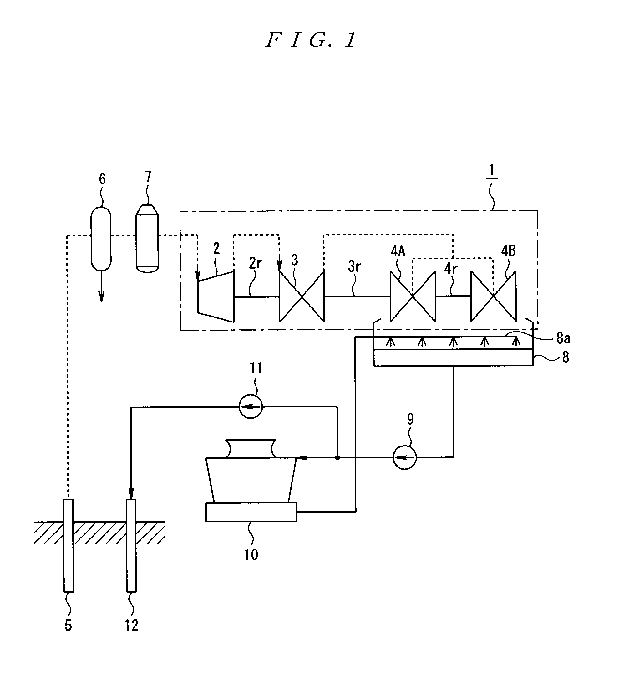
[0037]FIG. 1 is a schematic diagram showing a schematic configuration of a steam turbine to which the present invention may be applied. In FIG. 1, a reference numeral 1 denotes a steam turbine, which comprises a high-pressure turbine 2, a middle-pressure turbine 3, and two low-pressure turbines 4A and 4B. Among those, the geothermal steam supplied e.g. from a geothermal fluid production well 5 of a geothermal power plant is separated by a high-pressure separator 6 into steam and hot water. The separated steam is washed and supplied to the high-pressure turbine 2 through a scrubber 7 to remove mist. With the steam supplied to the high-pressure turbine 2, a turbine rotor 2r is rotated. The steam of which kinetic energy for rotating the turbine rotor 2r is released in the high-pressure turbine 2 is then supplied to the middle-pressure turbine 3 where a turbi...


PUM

PropertyMeasurementUnit
sizesaaaaaaaaaa
lengthaaaaaaaaaa
temperatureaaaaaaaaaa

Abstract

Provided are corrosive environment monitoring systems and methods whereby corrosive factors are measured in a steam turbine and a corrosive environment is correctly monitored. More specifically, provided is a corrosive environment monitoring system which measures corrosive factors having a part in damaging and deteriorating structural members in a steam turbine and which is configured in such a way that steam in the steam turbine is permitted to flow into the corrosive environment monitoring system. Furthermore, in the steam turbine, there are provided a condensing mechanism which condenses steam that has flowed in and a corrosive factor measuring device which is equipped with corrosive factor sensors that measure corrosive factors in condensed water generated by the condensing mechanism.

Description

TECHNICAL FIELD[0001]The present invention relates to a corrosive environment monitoring system and a corrosive environment monitoring method for measuring corrosive factors participating in damage and degradation of a structural member provided inside of a steam turbine. Related ArtBACKGROUND[0002]In a steam turbine, material degradation due to high-temperature heat degradation of a member caused by operating temperature, creep and thermal fatigue degradation, and material degradation resulting from corrosion damage to constructional members of the turbine caused by steam quality have became critical factors governing the life of the steam turbine.[0003]For the former case, it springs from material degradation of the member per se, and therefore it can non-destructively inspect and measure changes in hardness and precipitates of member materials, for understanding of the changes, during routine inspection, and compare the inspected and measured results with a previously acquired de...

Claims


Application Information

Patent Timeline
Patent Type & Authority Applications(United States)
IPC IPC(8): F01D25/00G06F19/00G08B21/00G01N31/22
CPCG01N17/02G01N2001/2282G01N2001/1037
Inventor KATO, HIDEOSAKAI, YOSHIHIRONAKAMURA, KENJIYAMASHITA, MITSUO
Owner FUJI ELECTRIC CO LTD
Why Eureka
Try Eureka