

Autoclave molding method and autoclave molding apparatus
- Summary
- Abstract
- Description
- Claims
- Application Information
AI Technical Summary
Benefits of technology
Problems solved by technology
Method used
Image

Examples
embodiment 1
[0065]Preferred embodiments of the autoclave molding method and the apparatus for the method of this invention are described in detail hereinafter based on the drawings. In the first embodiment, a thermosetting resin is used as the matrix.
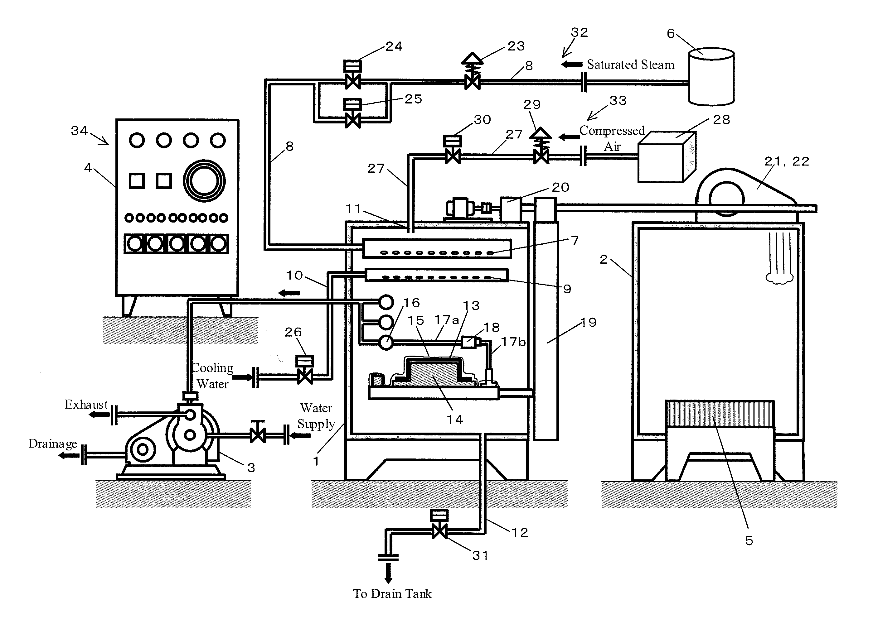
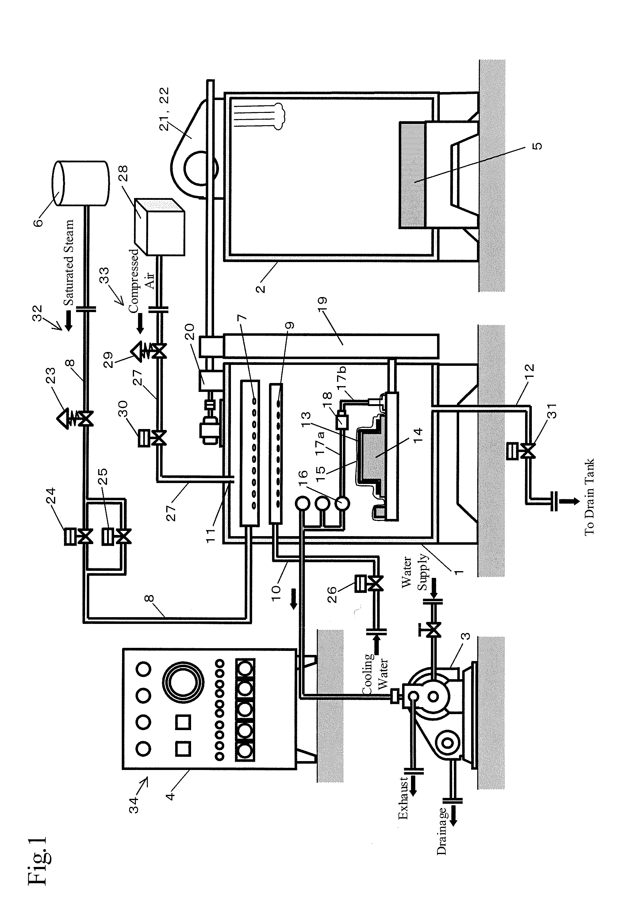
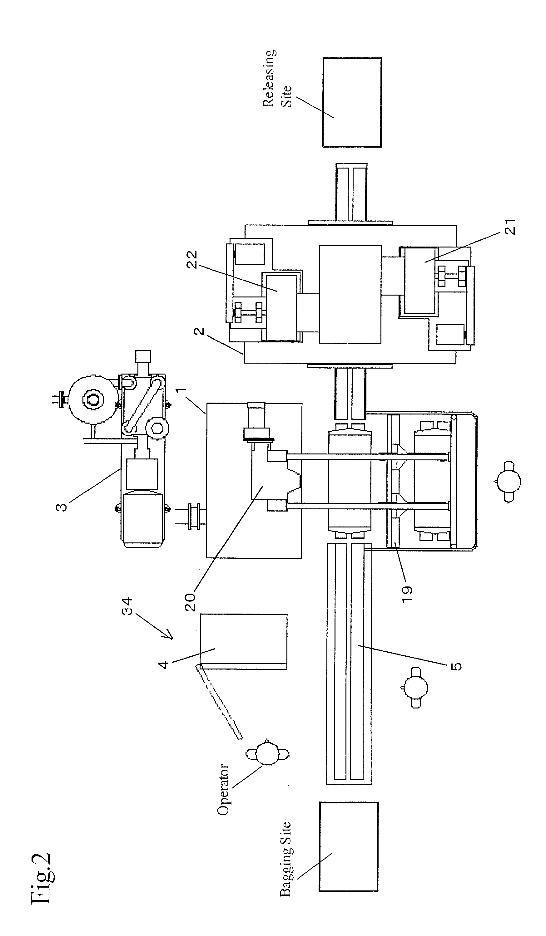
[0066]A schematic structure is shown in FIGS. 1 and 2 to show the whole autoclave apparatus of this invention.
[0067]The apparatus mainly comprises a molding chamber 1, a drying chamber 2, a water ring vacuum pump 3, a control panel 4, an automatic conveying line 5, namely, a conveyor, a boiler 6, pipes connected thereto, and a plurality of valves. Detailed structure of these will be described below.
[0068]Namely, the autoclave molding apparatus is to form a composite material 13 by placing the same in a vacuum bag 15 and then in the molding chamber 1, and heating and pressurizing the same. The composite material 13 is obtained by impregnating a fiber substrate, namely, a carbon fiber in this embodiment, with a thermosetting resin, namely, an epoxy r...
embodiment 2
[0113]The above-mentioned Embodiment 1 is a molding example in which the curing temperature condition is the temperature of the saturated steam, and the curing pressure condition is higher than that of the saturated steam.
[0114]When molding is performed under the condition of the curing pressure same as the pressure of the saturated steam, the air, nitrogen or the mixed gas of these having a predetermined pressure used as the supplemental pressurization source is not needed. Therefore, in this Embodiment 2, the need for the compressed air supplying means 33, which is arranged in the apparatus described in the Embodiment 1, is eliminated.
[0115]Now, detailed explanation is given hereinafter based on FIGS. 8 and 9. FIG. 8 is a pattern graph for controlling the temperature and the pressure over the time course, and charts of pressure of the saturated steam and the exhaust moving in synchronization with the progress of the pattern graph. The vertical axis of each of the charts shows a ga...
embodiment 3
[0125]Following is the description of the molding process on the condition that the curing pressure is lower than the saturated steam pressure. Where the structure is substantially same as that in the above-mentioned Embodiment 1, the relevant description is omitted in this description of the Embodiment 3.
[0126]As shown in FIG. 10, the saturated steam heating means 35 is arranged to heat the saturated steam to turn it into superheated steam. The saturated steam corresponding to the pressure of the curing condition is heated by the saturated steam heating means 35 to turn it into superheated steam so that the temperature of the curing condition can be obtained.
[0127]The saturated steam heating means 35 is an electric heater in this embodiment, and is arranged on the steam pipe 8. Alternatively, the steam pipe 8 may be branched at the upstream side of the pressure reduction valve 23 and the branch is arranged in a manner of winding around the steam pipe 8 at the downstream side of the...
PUM
| Property | Measurement | Unit |
|---|---|---|
| Temperature | aaaaa | aaaaa |
| Pressure | aaaaa | aaaaa |
Abstract
Description
Claims
Application Information