Metal plate to be heated by radiant heat transfer and method of manufacturing the same, and metal processed product having portion with different strength and method of manufacturing the same

a technology of metal processing and heat transfer, which is applied in the direction of domestic heating, solid-state devices, drying solid materials, etc., can solve the problems of poor productivity of gas heating furnaces or the like, inability to stabilize, and likely to spring back, so as to improve heating efficiency and reduce cost. , the effect of intensively heating only a specific portion of a metal pla

Active Publication Date: 2012-05-31
NIPPON STEEL CORP
View PDF11 Cites 15 Cited by
  • Summary
  • Abstract
  • Description
  • Claims
  • Application Information

AI Technical Summary

Benefits of technology

[0018]According to the present invention, it is possible to increase heating efficiency and to intensively heat only a specific portion of a metal plate by radiant heat transfer at lower cost and with higher productivity than conventionally. Moreover, there are many advantages such as a higher degree of freedom in component design as a metal processed product.

Problems solved by technology

However, products obtained through ordinary cold press forming have a problem that spring back is likely to occur therein due to an intrinsic stress and dimensional accuracy thereof is not stable.
As a heating method, a gas heating furnace or the like is generally used, but the gas heating furnace or the like is poor in productivity because of its low heating efficiency.
Therefore, to increase productivity, the facility needs to be made large, leading to increased cost.
However, when the shape of the metal plate is not a square but a profile shape, the current concentrates on a portion with a small sectional area, which has a problem that a desired region cannot be uniformly heated.
Incidentally, to uniformly heat a specific portion of the metal plate, laser heating is conceivable, but this has problems of high facility cost and poor productivity.

Method used


Image

  • Metal plate to be heated by radiant heat transfer and method of manufacturing the same, and metal processed product having portion with different strength and method of manufacturing the same
  • Metal plate to be heated by radiant heat transfer and method of manufacturing the same, and metal processed product having portion with different strength and method of manufacturing the same
  • Metal plate to be heated by radiant heat transfer and method of manufacturing the same, and metal processed product having portion with different strength and method of manufacturing the same

Examples


example 1

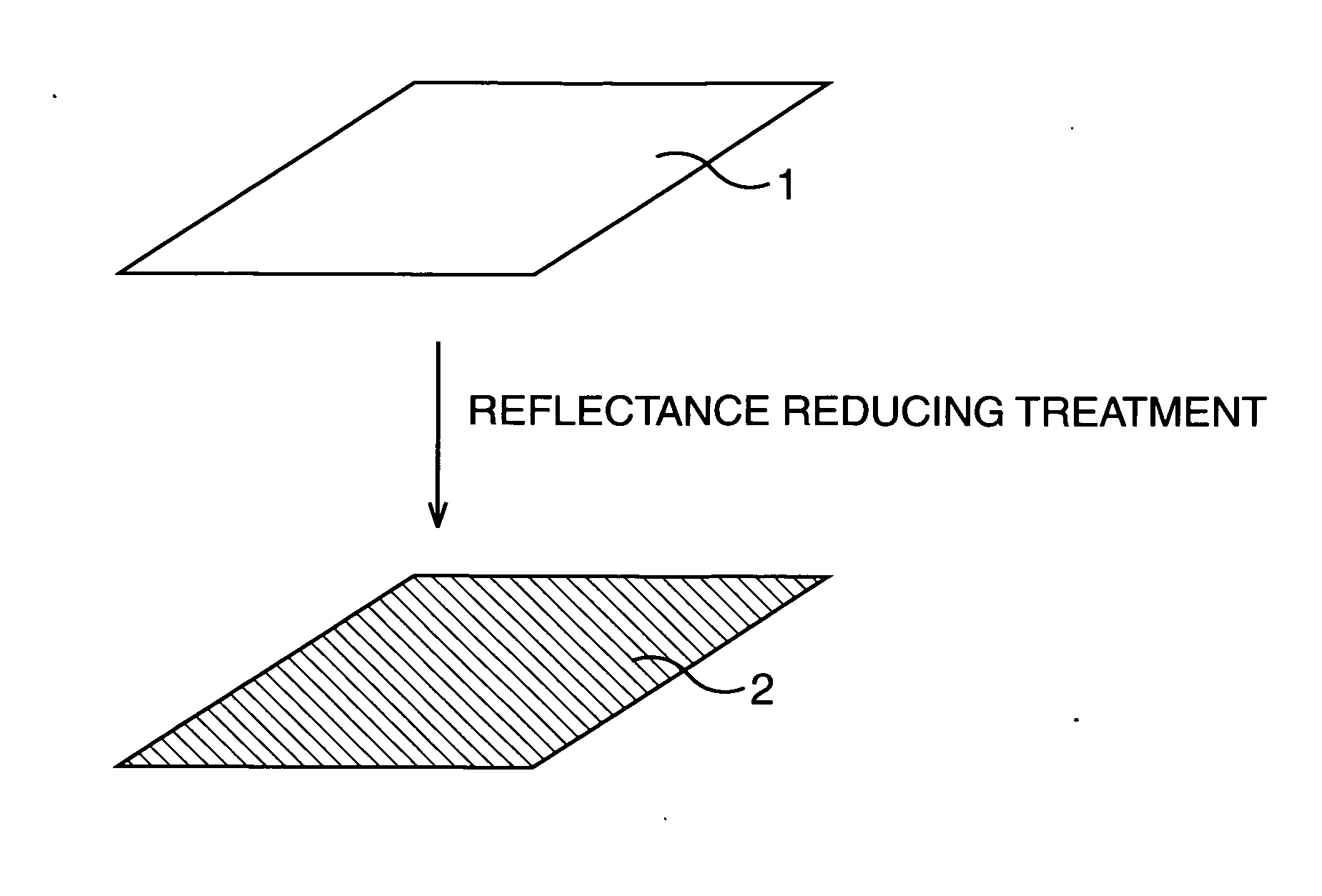
[0060]Table 1 summarizes effects obtained when the reflectance reducing treatment according to the present invention was applied to a metal plate. A steel plate with a 1.6 mm plate thickness was cut into a shape with a 170 mm short side and a 440 mm long side and was heated by radiant heat transfer from 20° C. to 850° C. by using a near-infrared lamp. A heating rate was found from a ratio between a temperature difference from 20° C. to 850° C. and the time required for heating. No. 1 to 10 are examples and No. 11 and others are comparative examples.

TABLE 1kind ofreflectanceheatingreducingconcrete treatmentreflectancerateNo.metal platetreatmentcontents(%)(° C. / sec)1hot-dippaintingapply aqueous solution1340galvanizingcontaining carbonblack subjected tohydrophilic treatment(Aqua-Black of TokaiCarbon)2hot-dipmetal coatingblack electroless13.538galvanizingby platingnickel plating3hot-diprougheningshot blast4023galvanizing(Ra = 0.8 μm)4hot-dippaintingapply13.937galvanizingpolyester / melami...

example 2

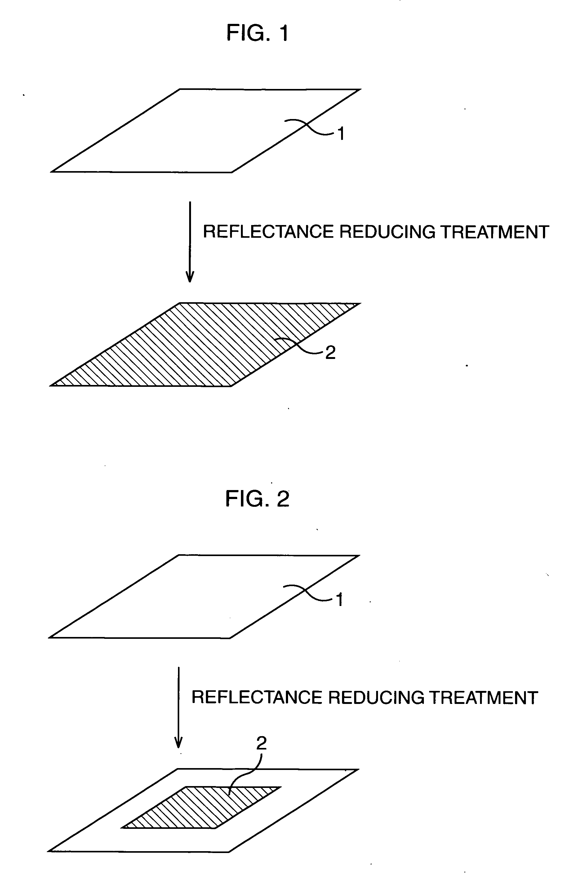
[0063]A hot-dip galvanized steel plate having a composition containing C, 0.22 mass %, Si: 0.15 mass %, Mn: 2.0 mass %, P: 0.02 mass % or less, S: 0.005 mass % or less, Ti: 0.023 mass %, Al: 0.035 mass %, B: 15 ppm, and N: 50 ppm or less, with the balance being Fe and inevitable impurities and having a 1.6 mm plate thickness was cut into the shape shown in FIG. 4. It has the size of a 100 mm short side, a 170 mm long side, and a 440 mm height. Next, 0.6 g / m2 blackening in which a 10% nickel chloride hexahydrate aqueous solution was applied, followed by water-washing and drying was applied to a center portion 12 of the hot-dip galvanized steel plate, thereby forming a portion having reduced reflectance and increased radiant heat transfer efficiency. A peripheral edge portion 13 was not subjected to the blackening.

[0064]Next, the hot-dip galvanized steel plate having undergone the blackening was heated by a near-infrared heating apparatus so that the center portion 12 was quickly heat...

example 3

[0067]A hot-dip galvanized steel plate having the same composition as that of the hot-dip galvanized steel plate used in the example 2 and having a 1.6 mm plate thickness was cut into the shape shown in FIG. 6. It had the size of a 100 mm short side, a 170 mm long side, and a 440 mm height. Next, a center portion 15 and a peripheral portion 16 of the cut hot-dip galvanized steel plate were subjected to blackening in which a 10% nickel chloride hexahydrate aqueous solution was applied, followed by water-washing and drying. At this time, the center portion 15 was subjected to 0.6 g / m2 blackening, and the peripheral portion 16 was subjected to 0.3 / m2 blackening, thereby forming portions where the reflectance was decreased and radiant heat transfer efficiency was increased as in the shape shown in FIG. 6. A peripheral edge portion 17 was not subjected to the blackening.

[0068]Next, the hot-dip galvanized steel plate having undergone the blackening was heated by a near-infrared heating ap...


PUM

PropertyMeasurementUnit
reflectanceaaaaaaaaaa

Abstract

On part of a surface of a metal plate that is to be heated by radiant heat transfer with a near-infrared ray, a region where reflectance for a radiant ray is made lower than that of the original surface of the metal plate is formed. As reflectance reducing treatment, painting or thermal spraying in a blackish color, plating in a blackish color, treatment for increasing roughness of the surface of the metal plate, blasting, etching, blackening, surface layer quality changing treatment of the metal plate, or the like can be adopted. The metal plate is turned into a heated metal plate partially having a different temperature by being heated by radiant heat transfer, and thereafter, the heated metal plate is subjected to thermal processing accompanied by cooling, for example, by hot stamping.

Description

TECHNICAL FIELD[0001]The present invention relates to a metal plate to be heated by radiant heat transfer excellent in workability and a method of manufacturing the same, and a metal processed product having a portion with different strength and a method of manufacturing the same. This application is based upon and claims the benefit of priority of the prior Japanese Patent Application No. 2009-183220, filed on Aug. 6, 2009 and Japanese Patent Application No. 2009-183221, filed on Aug. 6, 2009; the entire contents of which are incorporated herein by reference.BACKGROUND ART[0002]Many mechanical components such as automobile structural components are manufactured through pressing of a steel plate or other metal plates. However, products obtained through ordinary cold press forming have a problem that spring back is likely to occur therein due to an intrinsic stress and dimensional accuracy thereof is not stable. As one method to solve this problem, hot pressing called hot stamping ha...

Claims


Application Information

Patent Timeline
Patent Type & Authority Applications(United States)
IPC IPC(8): B21C1/00F27D11/12
CPCC21D8/0494C21D2221/00C22C38/001C22C38/002C22C38/02Y10T428/12229C22C38/06C22C38/14C23C4/04C23C4/18C22C38/04
Inventor KOBAYASHI, YOSHIFUMIKAWANO, KAZUYUKIITOH, YASUNORISUZUKI, SHINICHIYAMANAKA, SHINTARO
Owner NIPPON STEEL CORP
Why Eureka
Try Eureka