RFID enabled drawer refrigeration system

a refrigeration system and drawer technology, applied in the field of medication administration, can solve the problems of high cost of maintaining a large amount of inventory, large amount of labor, time-consuming, etc., and achieve the effect of robust electromagnetic field

Active Publication Date: 2012-06-07
MEPS REAL TIME
View PDF2 Cites 44 Cited by
  • Summary
  • Abstract
  • Description
  • Claims
  • Application Information

AI Technical Summary

Problems solved by technology

The initial purpose of such systems was to reduce medication errors associated with manual distribution and the high cost of maintaining a large amount of inventory.
While the cart exchange system is still in use for some medications, the activities of bringing up many new orders from the central pharmacy during the day, and having a large amount of unused medication being returned results in a large amount of labor.
The re-stocking of these medications needs to be done accurately, and is very time consuming.
Refrigeration is relatively expensive due to the power requirements and the refrigeration devices needed.
Medication cabinets as a whole are expensive and relatively large, each having its own computer equipment, power equipment, communication equipment, and each taking up valuable floor space.
This is an inefficient approach.
Such manual handling, examination, and research is time consuming.
Data transmission to the tag is not possible.
These tags are very low cost and are produced in enormous quantities.
Programming each one of the tags with information contained in the article to which they are attached involves further expense.
Another choice is an active RFID tag; however, such tags require an accompanying battery to provide power to activate the tag, thus increasing the expense of the tag and making them undesirable for use in a large number of applications.
Additionally, in the U.S. and in other countries, the frequency range within which such tags are permitted to operate is limited.
At this frequency range, the electromagnetic energy is less affected by liquids and other dielectric materials, but suffers from the limitation of a short interrogating distance.
Additionally, metal surfaces of the enclosures present a serious obstacle for the RF signals that need to be exchanged between RFID readers and RFID tags, making RFID tags located behind those metal surfaces difficult or impossible to detect.
In addition to the above, the detection range of the RFID systems is typically limited by signal strength to short ranges, frequently less than about thirty centimeters for 13.56 MHz systems.
However, such an antenna may be unwieldy and may increase the range of the radiated power beyond allowable limits.
Furthermore, these reader antennae are often located in stores or other locations where space is at a premium and it is expensive and inconvenient to use such large reader antennae.
In another possible solution, multiple small antennae may be used but such a configuration may be awkward to set up when space is at a premium and when wiring is preferred or required to be hidden.
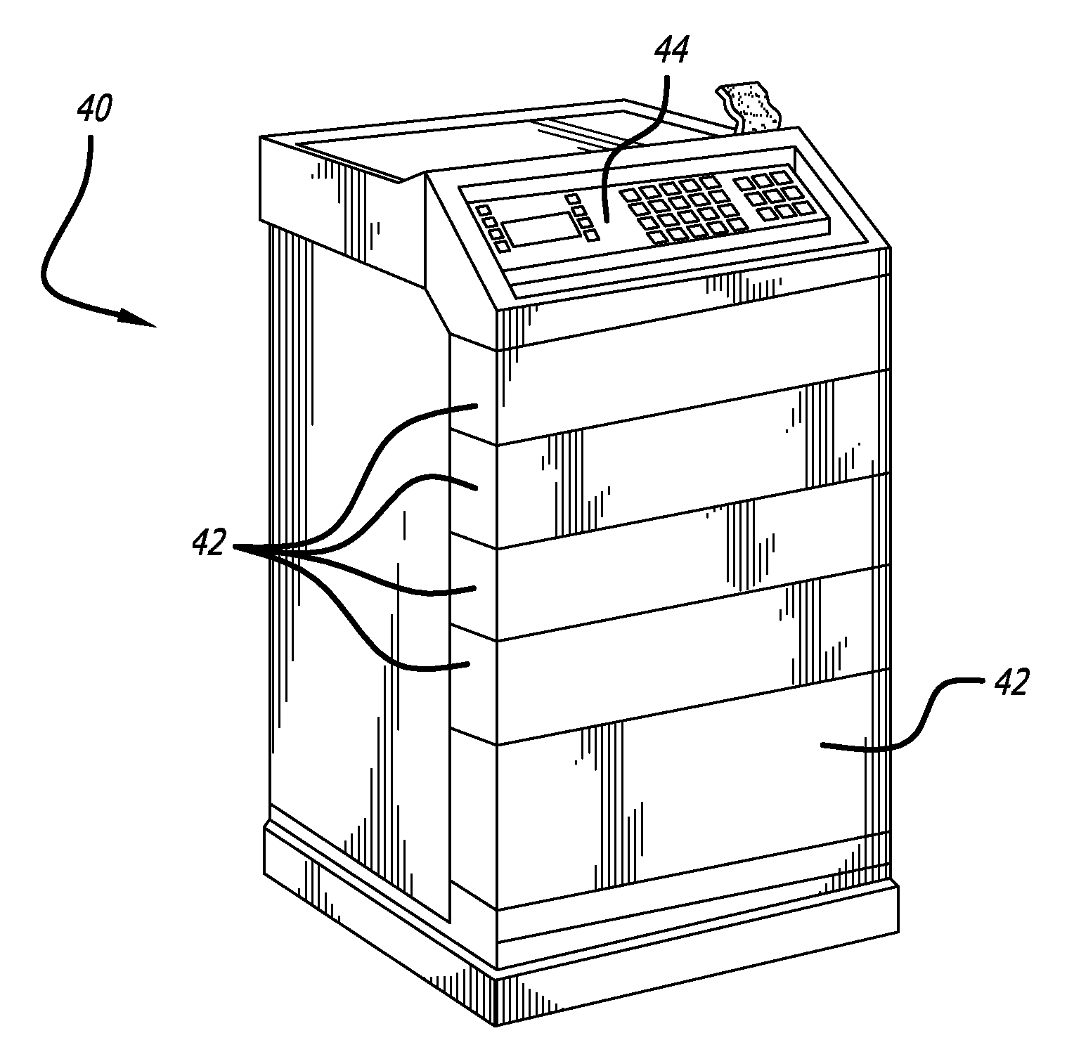
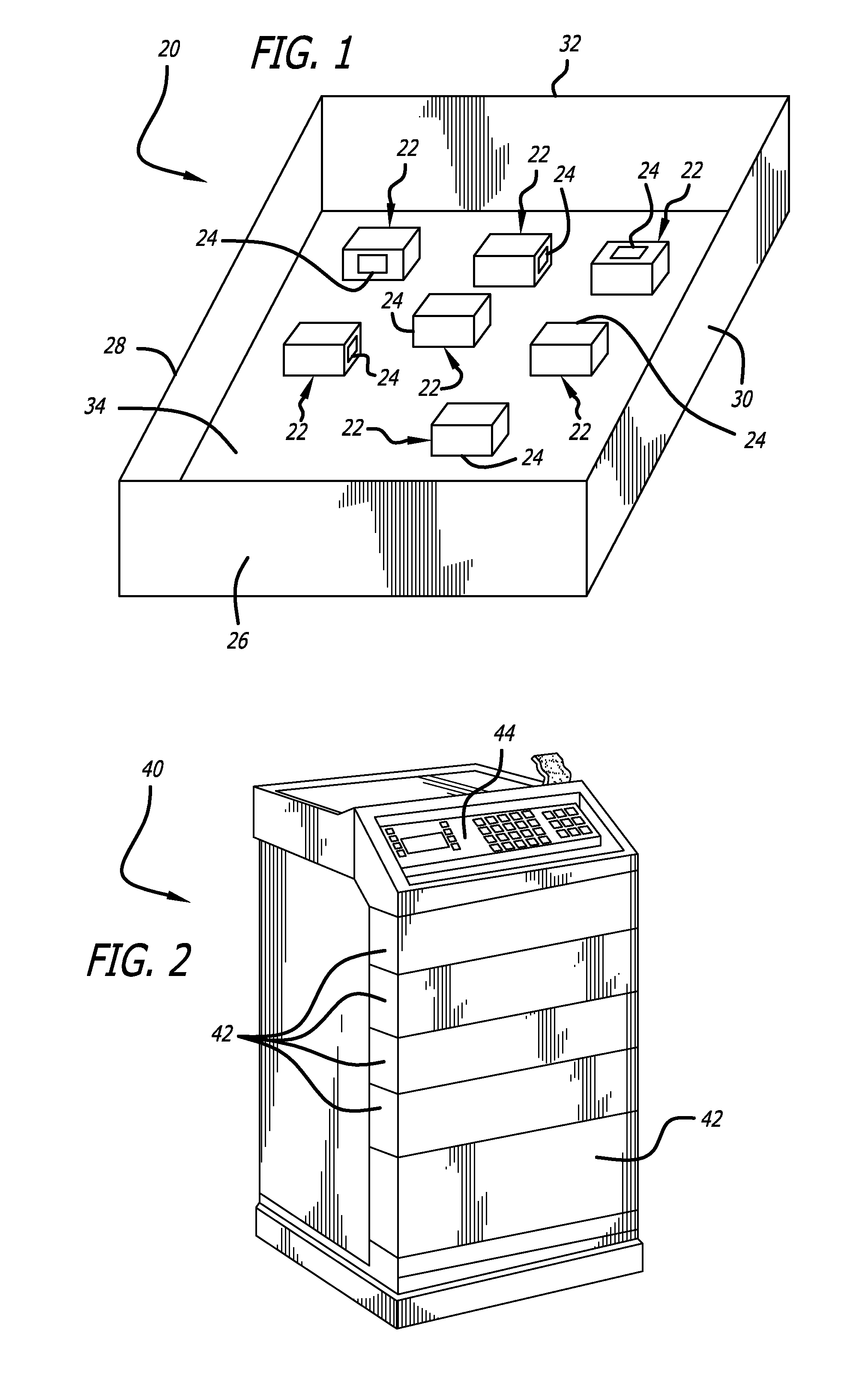
Cabinets such as these are typically made of metal, which can make the use of an external RFID system for identification of the stored articles difficult.
In some cases, such cabinets are locked due to the presence of narcotics or other medical articles or apparatus within them that are subject to a high theft rate.
Thus, manual identification of the cabinet contents is difficult due to the need to control access.
Providing an internal RFID system in such a cabinet can pose challenges.
In general, dead zones are areas in which the level of coupling between an RFID reader antenna and an RFID tag is not adequate for the system to perform a successful read of the tag.
Thus, articles placed in dead zones may not be detected thereby resulting in inaccurate tracking of tagged articles.
Often in the medical field, there is a need to read a large number of tags attached to articles in such an enclosure, and as mentioned above, such enclosures have limited access due to security reasons.
Generating such a robust EM energy field is not an easy task.
However, in the RFID field the usable frequencies of operation are strictly controlled and are limited.
Where the enclosure impedance changes due to the introduction or removal of articles to or from the enclosure, a static impedance matching circuit may not provide optimum energy transfer into the enclosure.
If the energy transfer and resulting RF field intensity within the enclosure were to fall below a threshold level, some or many of the tags on articles within the enclosure would not be activated to identify themselves, leaving an ineffective inventory system.
The use of high-power readers to locate and extract data from RFID tags is generally undesirable in health care facilities, although it may be acceptable in warehouses that are sparsely populated with workers, or in aircraft cargo holds.
Radiating a broad beam of EM energy at a large area, where that EM energy may stray into adjacent, more sensitive areas, is undesirable.
Additionally, this is a manual system that will require the services of one or more individuals, which can also be undesirable in facilities where staff is limited

Method used


Image

  • RFID enabled drawer refrigeration system
  • RFID enabled drawer refrigeration system
  • RFID enabled drawer refrigeration system

Examples


Embodiment Construction

[0069]Referring now in more detail to the exemplary drawings for purposes of illustrating embodiments of the invention, wherein like reference numerals designate corresponding or like elements among the several views, there is shown in FIG. 1 a schematic representation of a partial enclosure 20 in which a plurality of medical articles 22 are stored, each with a respective RFID tag 24 that has a unique identification number. The partial enclosure may comprise a drawer having a front 26, a left side 28, a right side 30, a rear 32, and a bottom 34. These articles are randomly distributed in the drawer with the RFID tags facing in various and random directions.

[0070]As used in regard to the embodiments herein, “reader” and “interrogator” refer to a device that may read or write / read. The data capture device is always referred to as a reader or an interrogator regardless of whether it can only read or is also capable of writing. A reader typically contains a radio frequency module (a tra...


PUM


Abstract

An automated system and associated method for storing medical items comprises a medication cabinet having at least one refrigerated drawer having a thermo-electric cooling (TEC) device and a non-refrigerated drawer. The refrigerated drawer design is such that cooling gradients throughout the drawer are minimized. Faraday cages are provided about each drawer to support separate RFID readers to monitor the medical items in each drawer. An automatic RFID data detection system determines the temperature requirements of medical items in the refrigerated drawer and controls the TEC device to maintain the required temperature. A temperature logging system for the refrigerated drawer is provided. A separate RFID reader determines if a temperature-controlled item has been placed in a non-refrigerated drawer and if so, an alert is provided.

Description

INCORPORATED MATERIAL[0001]This application incorporates U.S. Application No. 61 / 419,762, filed on Dec. 3, 2010, and U.S. application Ser. No. 12 / 631,861, filed on Dec. 7, 2009, and also incorporates U.S. Application No. 61 / 302,912, filed on Feb. 9, 2010, all of which are incorporated herein by reference.BACKGROUND[0002]The invention relates generally to the field of medication administration, and more particularly, to a medication administration system and associated method that provide identification, tracking, and temperature control over medications.[0003]Medication dispensing systems have been in use for many years. The initial purpose of such systems was to reduce medication errors associated with manual distribution and the high cost of maintaining a large amount of inventory. Current systems present many advantages, including lower costs associated with pharmaceutical distribution, improved inventory control, substance control, automated documentation, further reduction of e...

Claims


Application Information

Patent Timeline
Patent Type & Authority Applications(United States)
IPC IPC(8): F25B21/02G16H20/13
CPCG06K19/07749G06F19/3462F28F27/00F28F9/00A61J1/00H04Q2209/47H04Q9/00G16H20/13
Inventor HUSSAIN, SHARIQELIZONDO, PAUL M.GOLDE, TIMOTHYCAPUTO, JIMMY
Owner MEPS REAL TIME
Why Eureka
Try Eureka