
Subterranean formation deformation monitoring systems

a monitoring system and subterranean technology, applied in the field of subterranean formation deformation monitoring systems, can solve the problems of easy to see subsurface subsidence, lose air gap, increase risk, etc., and achieve the effect of greater deformation detail

Active Publication Date: 2012-06-07
CONOCOPHILLIPS CO +1
View PDF3 Cites 23 Cited by
  • Summary
  • Abstract
  • Description
  • Claims
  • Application Information

AI Technical Summary

Benefits of technology

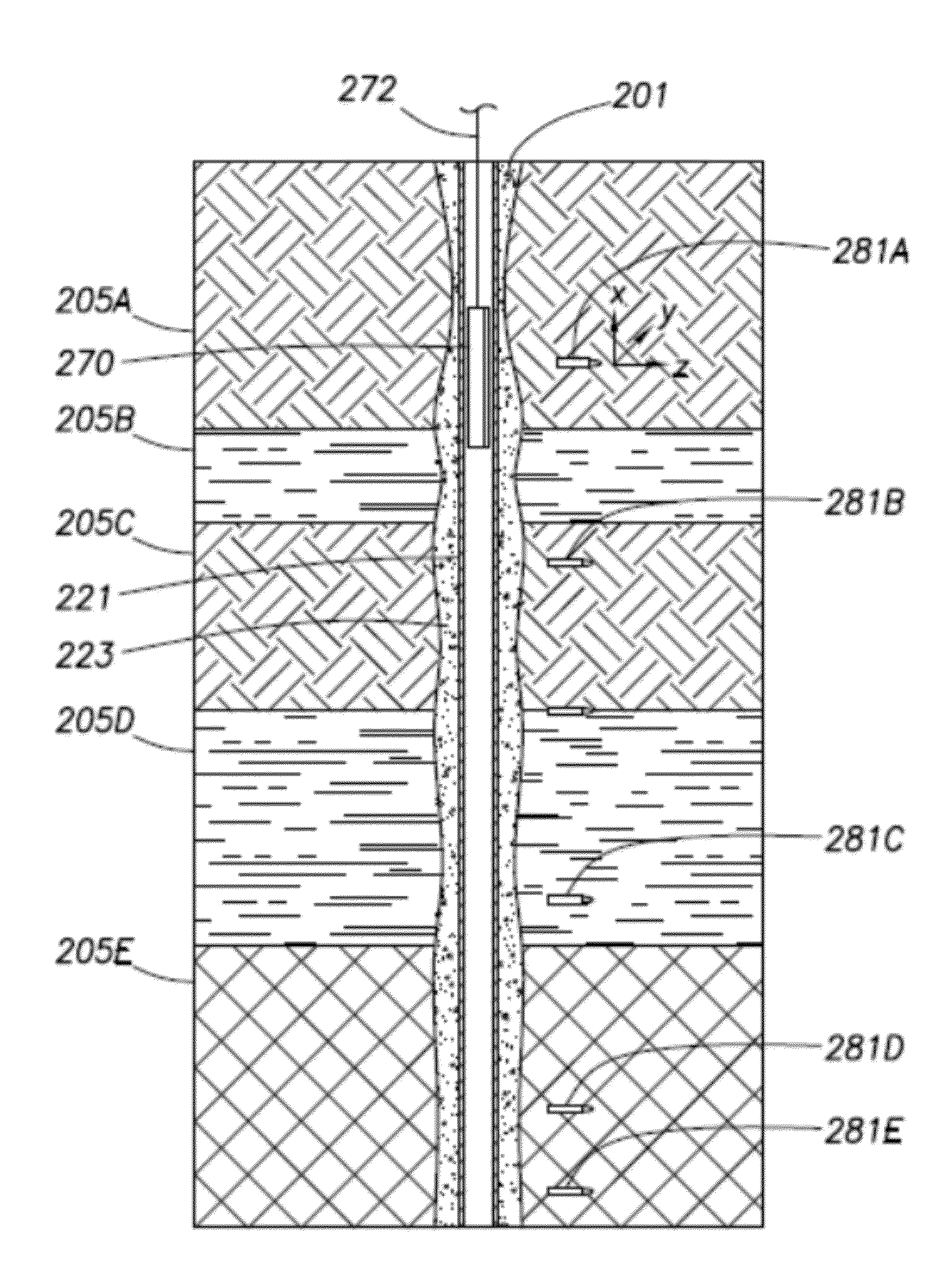
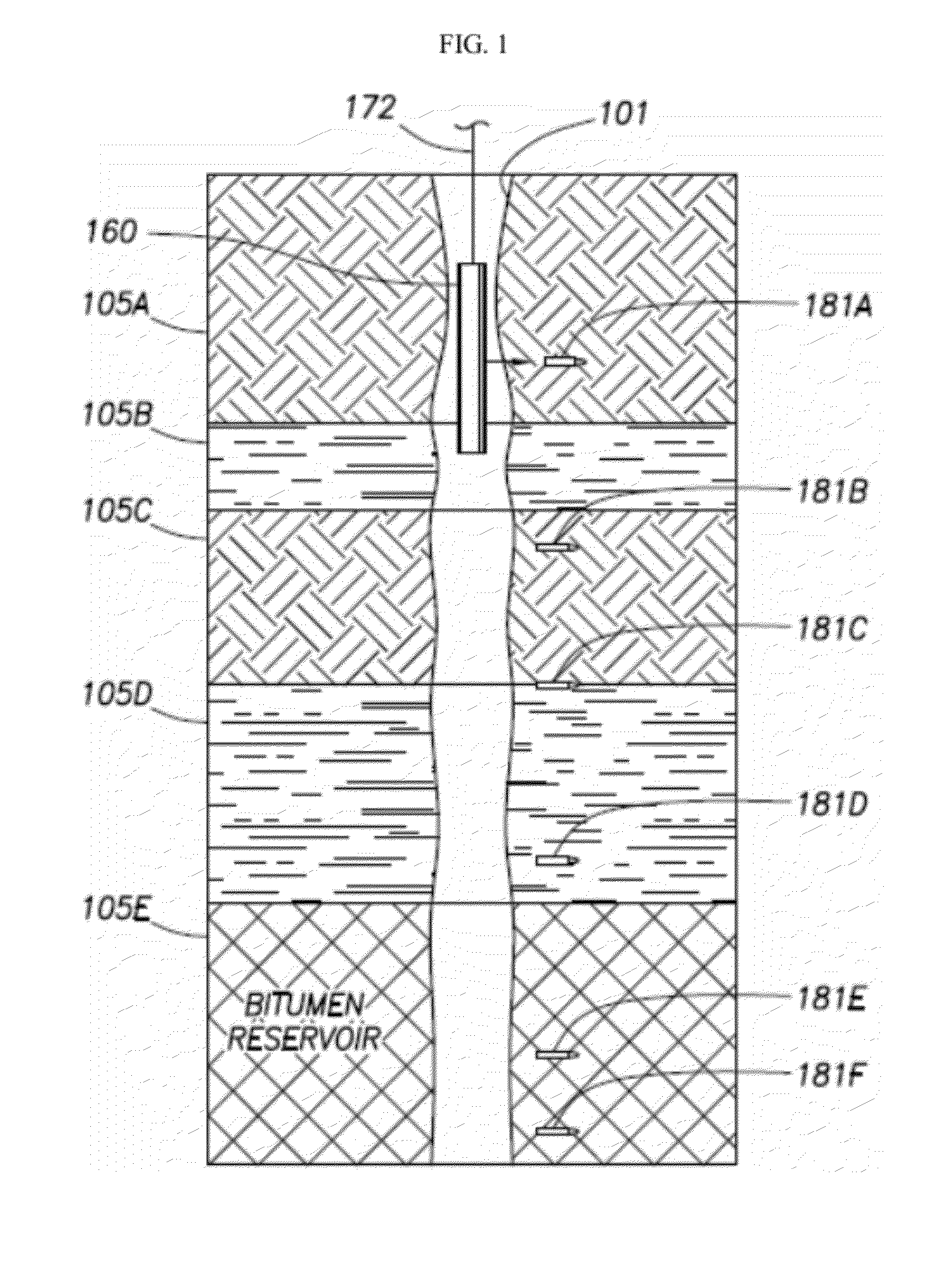
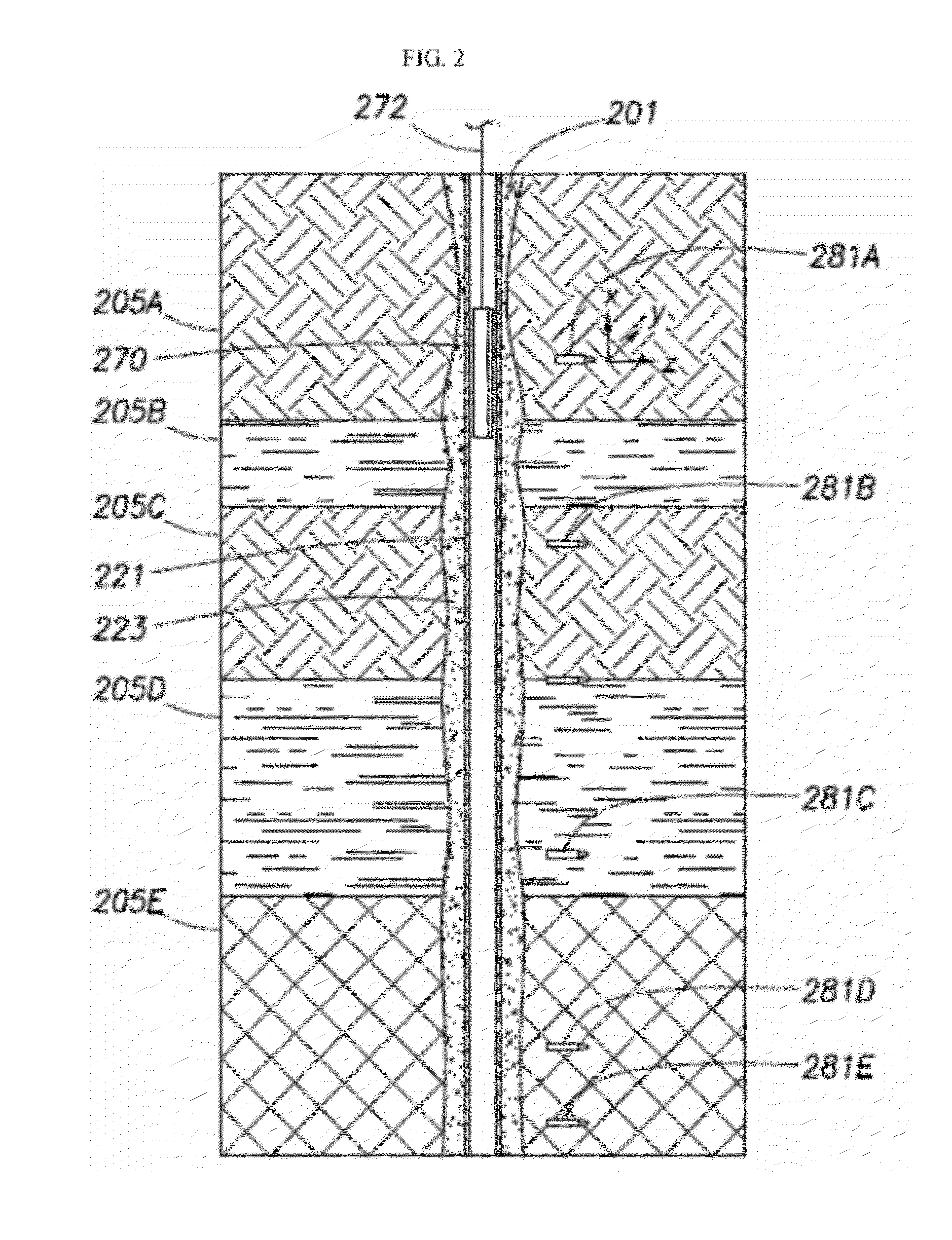
[0031]One embodiment is a method for measuring deformation in a subterranean formation comprising the steps of introducing a plurality of magnetic markers into a well hole of a subterranean formation at different depths, such that each of the plurality of magnetic markers are about equally spaced-apart from one another in depth. A logging tool is introduced into said well hole, wherein the logging tool comprises an elongated body and at least two magnetic sensors therein. Preferably, those sensors are spaced apart at about the same spacing at the magnetic bullets, which improves the accuracy of measurements. A first spatial position of each magnetic marker is determined and recorded, and then compared with subsequent positions over time. Such measurements repeated over time can be used to calculate the amount of deformation of the formation, since any deformation will cause the markers to move up or down and / or change orientation or move sideways.
[0047]Preferably the magnetic sensors are magnetometers, such as are typically employed in ground-based electromagnetic geophysical surveys. Either scalor or vector magnetometers, or combinations thereof can be used. Scalar magnetometers measure the total strength of the magnetic field to which they are subjected, and vector magnetometers have the capability to measure the component of the magnetic field in a particular direction. For example, the use of three orthogonal vector magnetometers allows the magnetic field strength, inclination and declination to be uniquely defined. This is particularly useful in the methods of the invention because such a device will allow for an indication of both horizontal and vertical movements and thus provide much greater deformation detail that the currently used RTM method.

Problems solved by technology

The reduction in pressure and fluid loss may cause subsidence and compaction of the subterranean formation, and the risk increases when the formation has relatively high porosity and a low compressive strength.
It is difficult to observe the compaction of a hydrocarbon reservoir, but subsidence at the surface is often easy to see.
For example, water can encroach on previously dry land, an offshore platform can lose its air gap between the high waves and the bottom deck, wellheads and casing may begin to protrude from the surface, or surface structures can sink.
An excessive amount of subsidence may result in well casing failure or rig collapse, affect cap rock integrity and can permanently damage the permeability and hydrocarbon producing capability of a subterranean formation if the interstitial pores are irreparably closed.
Where high volumes of water, gas, and / or steam are injected into a reservoir, rock formations can dilate, thus causing surface heave.
Excessive surface heave and reservoir dilation also pose a risk to surface facilities, well casing failures, and cap rock integrity.
Unfortunately, however, there are no existing technologies to date that can measure this effect in the reservoir.
However, performing this type of survey over large areas can be prohibitively expensive.
The InSAR method has limitations, though, because growth of vegetation between satellite passes can cause interpretation problems over open fields.
Offshore, the subsidence bowl is not easily accessed.
Subsidence also affects pipelines and other structures on the seabed.
Heave is usually more difficult to measure than subsidence.
But these methods have largely been dis-continued as insufficiently accurate.
The best place to put the markers is in a vertical monitor well because deviated wells introduce an error in the position of the marker, depending on the orientation of the gun when the bullets are fired.
Unfortunately, although a very useful technique, the use of the radioactive markers poses an environmental exposure hazard under some circumstances.
For example, when a subterranean formation comprises high density rock, the bullets may bounce and can become lost or partially lodged in the wall of the borehole.
Other stray radioactive marker bullets may simply fall to the bottom of the borehole.
When the next section of the borehole is drilled, some of the stray radioactive marker bullets may be crushed, exposing the drilling mud to radioactive particles, risking human exposure or exposure to the external environment and / or aquifers.
Additionally, the RMT of the prior art only provide rough information about changes in the depth of the radioactive marker.

Method used


Image

  • Subterranean formation deformation monitoring systems
  • Subterranean formation deformation monitoring systems
  • Subterranean formation deformation monitoring systems

Examples


example 1

Field Test

[0082]A field test was performed to determine if magnetic markers can be placed in the formation using a modified, side wall percussion core gun, the explosive powder gram charge best suited for the different formations, the associated marker capsule penetration depths and detection capabilities of both the ORIT and the CBIL logs. The logs were used to both verify the signal after the magnets were placed and also to understand the penetration depth and damaged zone around the target.

[0083]The gun normally shoots an open topped, tethered cylinder into a formation in order to sample the formation, and then the core sample is retrieved. Here, the cylinder was replaced with an untethered magnetic bullet, as shown in FIG. 5. Various magnetic cores were placed inside specially manufactured hardened steel casings composed of a bottom or base, and pointed top that screwed over the base.

[0084]A 25 shot core gun was loaded with minimally modified drivers (designed to release the bul...


PUM


Abstract

Method, devices and systems are provided for measuring deformation in subterranean formations. Such methods include introduction of spaced-apart depth magnetic markers along the longitudinal length of a well bore and measuring the position of each depth marker over time so as to determine deformation of the subterranean formation. In certain embodiments, depth markers comprise rare earth magnets. In further embodiments, orientation of each magnetic bullet is determined over time to determine the change in orientation of each magnetic bullet. Advantages of the methods and devices herein include, but are not limited to, improved accuracy and reliability of deformation measurements and reduced environmental impact due to the avoidance of radioactive markers used by the present invention.

Description

CROSS-REFERENCE TO RELATED APPLICATIONS[0001]This application claims priority to 61 / 312,130, filed Mar. 9, 2010, which is incorporated in its entirety by reference.FEDERALLY SPONSORED RESEARCH STATEMENT[0002]Not applicable.REFERENCE TO MICROFICHE APPENDIX[0003]Not applicable.FIELD OF THE INVENTION[0004]The present invention relates generally to a method, system and devices for measuring and / or monitoring deformation in subterranean formations. More particularly, but not by way of limitation, embodiments of the present invention include methods and systems for measuring changes in spatial position and / or orientation of a plurality of depth markers over time using a logging tool.BACKGROUND[0005]The production of water and hydrocarbon fluids from subterranean formations reduces reservoir pressure and removes fluids from the interstitial pores of the subterranean formation. The reduction in pressure and fluid loss may cause subsidence and compaction of the subterranean formation, and th...

Claims


Application Information

Patent Timeline
IPC IPC(8): E21B47/00H01F7/06H01F7/02G01V3/18E21B47/026E21B47/04
CPCE21B47/026E21B47/04E21B47/1015E21B47/02216G01V3/081
Inventor TOMBERLIN, TIMOTHY A.VANDAL, BRYAN A.BYERLEY, GRANT W.LINKEWICH, ZACHARY L.A.
Owner CONOCOPHILLIPS CO
Learn More