
Dual-performance low noise amplifier for satellite-based radiofrequency communication

a radiofrequency communication and amplifier technology, applied in the direction of electrical equipment, electrical equipment contruction details, cooling/ventilation/heating modification, etc., can solve the problems of difficult to obtain new allocations of channels in the frequency range of 1 ghz to 18 ghz as covered by these bands, complex control of antenna tracking, and difficulty in obtaining new allocations of channels. achieve the effect of low noise amplifier and enhanced characteristics

Active Publication Date: 2012-06-07
CALLISTO FRANCE
View PDF24 Cites 7 Cited by
  • Summary
  • Abstract
  • Description
  • Claims
  • Application Information

AI Technical Summary

Benefits of technology

[0034]Thus the low noise amplifier is able to be conceived with reduced dimensions despite the required cryogenic cooler, and having at least two modes, one of which operates without the cryogenic cooler operating. This mode reduces the energy consumption without compromising on the link budget with the satellite, and without a reduction in the reliability of the low noise amplifier.
[0069]In this situation, the risks on the link budget of a degradation of signal to noise ratio not detected, or not detected early enough to enable enhanced mode from normal mode, are mitigated.

Problems solved by technology

Due to the congestion of radio frequency bands currently used for communication with satellites, bands L, S, C and Ku, and with X-band reserved for military applications, it has become very difficult to obtain new allocations of channels in the frequency range of 1 GHz to 18 GHz as covered by these bands.
However, the control of the antenna tracking is complex not only because of the antenna size but also because of their high directivity.
Higher frequencies for communications is not without its difficulties because the high-frequency signals are in general (and especially the frequency bands K, Ka) sensitive to atmospheric phenomena.
The signals are weakened especially by humidity and the presence of clouds or rain.
In the worst cases the signals from a satellite cannot be intelligibly received and the communication link is no longer available.
Relatively simple to implement as long as this feature was built-in at the transmitter at the design stage, however, this solution causes interference and rapidly increases rates of intermodulation levels, which limits the possibilities of its use.
This solution is relatively complex to implement, lacks responsiveness and above all implies a lower transfer rate that may be incompatible with the expected service.
These solutions are very effective as they allow communications at the initial performance levels, but they are complex and imply a high cost due to the back-up ground stations.
Atmospheric conditions leading to deterioration of propagation are generally localized and temporary, with the result that the systems are designed with significantly higher performance ratings than is required for a large proportion of their operational life.
The resulting increase in the complexity of the components and their maintenance, results in a significant increase in their build cost, operational costs and in a lower reliability.

Method used


Image

  • Dual-performance low noise amplifier for satellite-based radiofrequency communication
  • Dual-performance low noise amplifier for satellite-based radiofrequency communication
  • Dual-performance low noise amplifier for satellite-based radiofrequency communication

Examples


Embodiment Construction

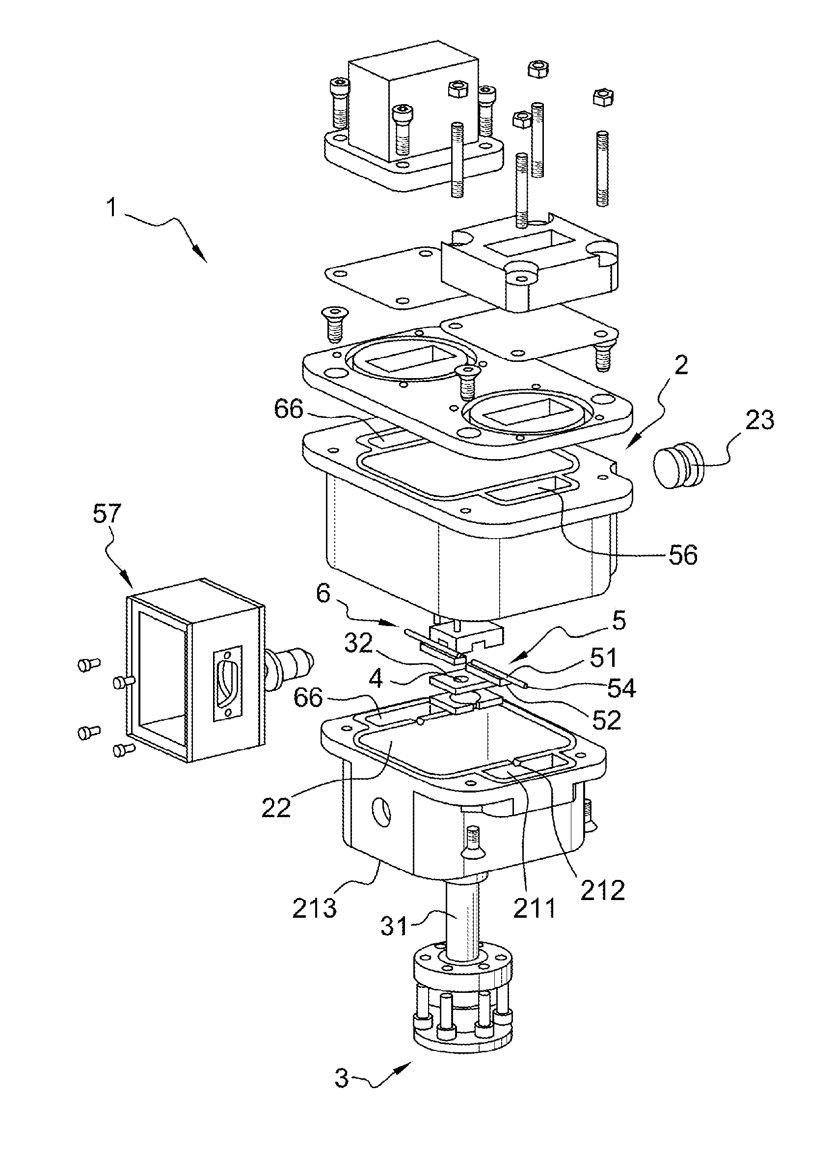
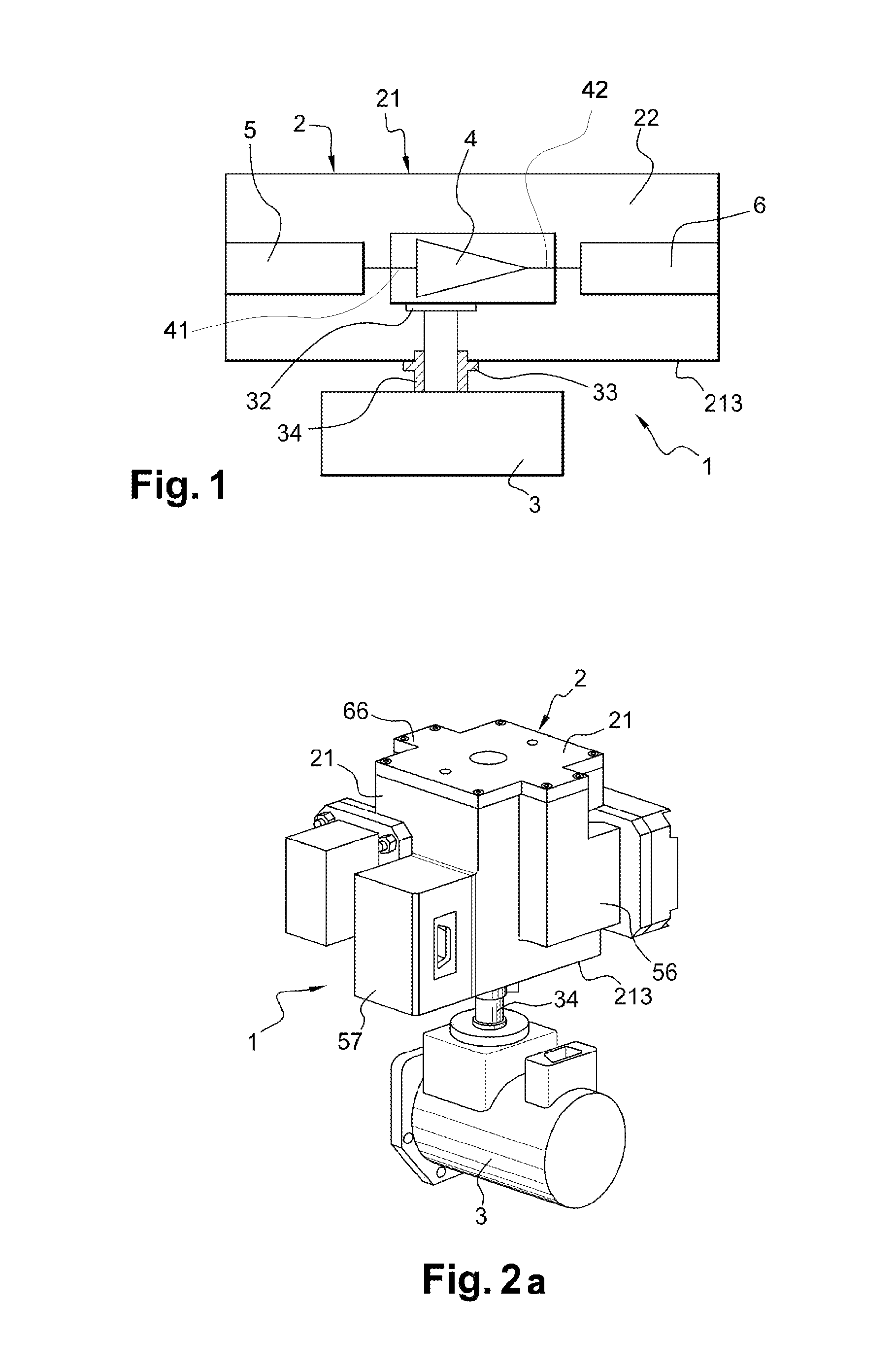
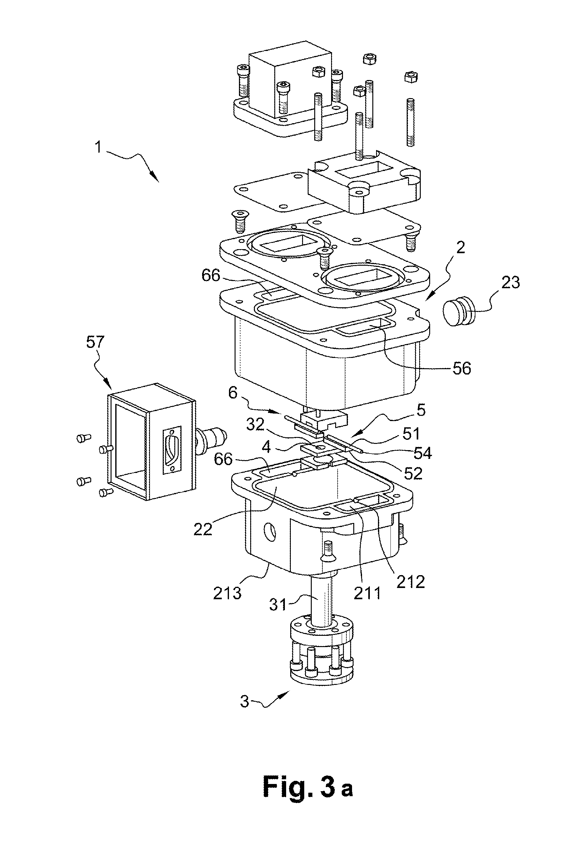
[0078]As shown schematically in FIG. 1 and in the perspective views in FIGS. 2a and 2b of an assembled amplifier, a low noise amplifier 1 according to the invention mainly comprises an insulating enclosure or cryostat 2, within which is enclosed an amplifier 4, an input coupler 5, connected to an input 41 of the amplifier 4, and an output coupler 6 connected to an output 42 of the amplifier 4, and a cold source such as a cryogenic cooler 3 on the outside of the cryostat.

[0079]The low noise amplifier 1 to be implemented, is such as those intended for integration in a conventional receiver chain (not shown) at atmospheric conditions, for the reception of RF signals from a satellite.

[0080]A cold finger 31 of the cryogenic cooler 3 traverses through the cryostat wall 21 so that a mounting surface 32 of the cold finger inside the cryostat 2 is in direct contact with a surface of the amplifier 4, or at least with a mounting plate supporting the amplifier.

[0081]The cryogenic cooler can be ...


PUM


Abstract

A low noise amplifier device for receiving a radio frequency signal from a satellite contains an amplifier kept in a sealed chamber in a cryostat, and a cryogenic cooler mounted on the outside of the cryostat. The amplifier is: maintained in the sealed chamber attached to a cold finger of the cryogenic cooler, made of a material with good heat conductivity and without direct contact with the wall of the cryostat; connected to the input and output coupler, each traversing the wall of the cryostat; functional at room temperature and at least one cryogenic temperature well below room temperature; and the sealed chamber of the cryostat contains a gas at a pressure between a pressure close to the pressure outside the cryostat and 0.1 millibar.

Description

FIELD OF INVENTION[0001]The present invention relates to the field of equipment used to communicate between satellites and general space objects, and fixed or mobile ground stations.[0002]More particularly, the invention relates to a high frequency low noise amplifier used in RF reception chains.[0003]The invention also relates to a method of implementation of the amplifier of the invention, to improve the quality of communications between a satellite or a space object and a ground station.BACKGROUND OF INVENTION[0004]Today the communications between the ground and moving objects above the earth's atmosphere (satellites and space objects in general) are made almost exclusively by radio frequency signals and because of the increasing demand for channels and bandwidth, higher and higher frequencies are used.[0005]Due to the congestion of radio frequency bands currently used for communication with satellites, bands L, S, C and Ku, and with X-band reserved for military applications, it ...

Claims


Application Information

Patent Timeline
IPC IPC(8): H05K7/20
CPCH03F3/189H03F1/26
Inventor RAWSON, STEPHENFAUROUX, BENOITRAYET, REMIBONHOURE, THOMASCHAMBON, CEDRIC
Owner CALLISTO FRANCE
Learn More