
Triaxial antenna for microwave tissue ablation

Inactive Publication Date: 2012-06-07
NEUWAVE MEDICAL
View PDF8 Cites 27 Cited by
  • Summary
  • Abstract
  • Description
  • Claims
  • Application Information

AI Technical Summary

Benefits of technology

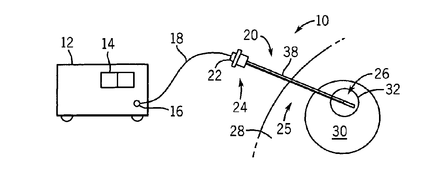
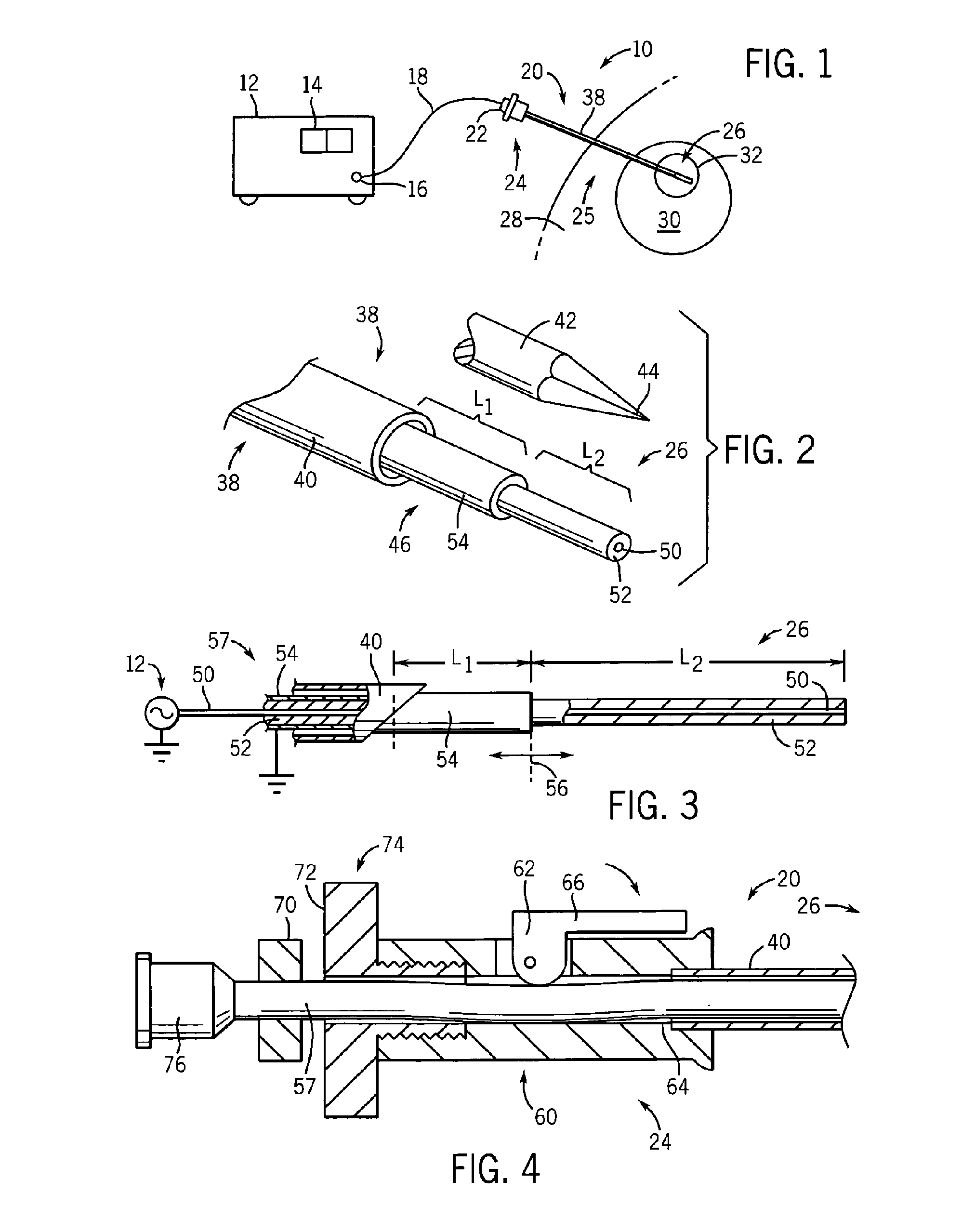
[0017]The present invention provides a triaxial microwave probe design for MWA where the outer conductor allows improved tuning of the antenna to reduce reflected energy through the feeder line. This improved tuning reduces heating of the feeder line allowing more power to be applied to the tissue and / or a smaller feed line to be used. Further, the outer conductor may slide with respect to the inner conductors to permit adjustment of the tuning in vivo to correct for effects of the tissue on the tuning.
[0018]Specifically, the present invention provides a probe for microwave ablation having a first conductor and a tubular second conductor coaxially around the first conductor but insulated therefrom. A tubular third conductor is fit coaxially around the first and second conductors. The first conductor may extend beyond the second conductor into tissue when a proximal end of the probe is inserted into a body for microwave ablation. The second conductor may extend beyond the third conductor into the tissue to provide improved tuning of the probe limiting power dissipated in the probe outside of the exposed portions of the first and second conductors.
[0019]Thus, it is one object of at least one embodiment of the invention to provide improved tuning of an MWA device to provide greater power to a lesion without risking damage to the feed line or burning of tissue about the feed line and / or to allow smaller feed lines in microwave ablation.

Problems solved by technology

However, MWA can produce greater and more rapid heating and can easily support the use of multiple probes because current flow between the probes can be limited.
Unfortunately, current MFA equipment produces relatively small lesions because of practical limits in power and treatment time.
Power is limited by the current carrying capacity of the small gauge feeder line as it passes through the patient to the site of the necrosis.
Larger feeder lines are undesirable because they are not easily inserted percutaneously.
Heating of the feeder line at high powers can also lead to burns around the insertion point of the MWA probe.
While many people with Barrett's are asymptomatic and most will never progress to cancer, esophageal adenocarcinoma is often deadly as the condition is usually diagnosed late and the current treatments are not effective.
Blood loss during surgery is a substantial clinical problem.
Resection of multiple tissue types in the neck, chest, abdomen, pelvis, and extremities are associated with blood loss that can be acutely life-threatening from hemodynamic effects, or if the blood loss is severe enough, can require transfusions.
This can be problematic from an immunological point of view during cancer surgery.
For example, increased blood loss requiring transfusions during hepatic resection increases post-resection mortality.
Blood loss is also a major problem during surgery for sharp or blunt trauma, in orthopedic surgery, and in gynecologic and obstetrical procedures.
Limitations of the above techniques center on the need for ground pads on the skin of the patient to provide a return path for the current, as well as the undesirable stimulation of the nervous system as cuts are being made; this usually requires injection of a temporary paralyzing agent.
Limitations of tissue impedance, particularly as the tissue becomes desiccated or charred during the course of the procedure, limit the amount of current, and hence the amount of ablative power, that can be applied to the tissue.
This in turn limits the size of vessels that can be effectively shut down.
Thus current procedures are limited when applied to resection of tumors from highly-vascularized organs, e.g. liver.
Furthermore, the limitations of current and power limit the speed at which these procedures can be performed.
Varicose veins are a common medical condition that affect up to 60% of all Americans, and represent a significant health and cosmetic problem.
Symptomatically, dilated varicose veins (usually the greater saphenous vein) can cause pain, cramping, itching, swelling, skin changes, venous stasis ulcers, and aching.
Surgical techniques can be technically challenging and more invasive than energy delivery techniques or sclerotherapy.
Sclerotherapy is limited in the accuracy by which substances may be administered.
Laser techniques can cause the vein to become extremely hot, which increases the probability of burns to the skin and subcutaneous tissues as well as perforation of the vein.
Radiofrequency techniques are relatively slow to heat, require ground pads to be placed on the patient and are not precise.

Method used


Image

  • Triaxial antenna for microwave tissue ablation
  • Triaxial antenna for microwave tissue ablation
  • Triaxial antenna for microwave tissue ablation

Examples


first embodiment

[0121]As illustrated in FIG. 15, the present disclosure comprises a thin metallic wire antenna 4 positioned inside the vessel 3 by a non-radiating catheter 5. The antenna 4 may be purely metallic or contain a core or sections of ferrite or similar material to enhance the heating effect. For small, tortuous veins, the antenna / catheter should be flexible enough to migrate therethrough. An external microwave source 1 positioned proximate the skin surface 2 directs energy at the wire antenna 4 causing the antenna 4 to radiate locally, thereby focusing the microwave energy on the wall of the vessel 3 to heat and ablate the vessel 3. The length L 1 of the antenna 4 is arbitrary. The placement catheter 5 is located at the proximal end 6.

second embodiment

[0122]As illustrated in FIG. 16, the present disclosure comprises a coaxial cable 9 which feeds the radiating antenna 7 directly with microwave energy. That energy is radiated by the antenna 7 to the wall of the vessel 3. The antenna length L 2 is fixed by the frequency of the microwave energy applied.

third embodiment

[0123]As illustrated in FIG. 17, the present disclosure comprises an external microwave source 10 controlled in such a way as to focus radiated energy in a small volume 11 onto the vessel 3. The energy is applied transcutaneously.

[0124]In any of the three embodiments described above, a device such as a balloon may be used to assist in providing generally uniform energy delivery in the vessel. As illustrated in FIG. 18, the balloon 12, comprised of conductive material such as Mylar, is shown in use in the vessel 3 to hold the position of the antenna 7 relative to the vessel wall.

[0125]Further, the vascular method and system of the present disclosure may include the use of an ultrasound probe or other imaging system or device to guide the antennas into place in the vessels. The ultrasound probe may also house the microwave source, such as the external microwave source 1 shown in FIG. 15, or external microwave source 10 shown in FIG. 17. The ultrasound probe and / or the external microwa...


PUM


Abstract

An improved antenna for microwave ablation uses a triaxial design which reduces reflected energy allowing higher power ablation and / or a smaller diameter feeder line to the antenna.

Description

CROSS-REFERENCE TO RELATED APPLICATION[0001]This application is[0002]1) a Continuation-in-part of U.S. patent application Ser. No. 13 / 153,974, filed Aug. 30, 2011, which A) is a Continuation of abandoned U.S. patent application Ser. No. 11 / 440,331, filed May 24, 2006, which is a Continuation-in-Part of pending U.S. patent application Ser. No. 10 / 834,802, filed Apr. 29, 2004 (now U.S. Pat. No. 7,101,369, which issued Sep. 5, 2006), B) claims priority to expired U.S. Provisional Patent Application No. 60 / 684,065, filed May 24, 2005, and to expired U.S. Provisional Patent Application No. 60 / 690,370, filed Jun. 14, 2005, and to expired U.S. Provisional Patent Application No. 60 / 702,393, filed Jul. 25, 2005, and to expired U.S. Provisional Patent Application No. 60 / 707,797, filed Aug. 12, 2005, and to expired U.S. Provisional Patent Application No. 60 / 710,276, filed Aug. 22, 2005, and to expired U.S. Provisional Patent Application No. 60 / 710,815, filed Aug. 24, 2005, C) is a Continuation...

Claims


Application Information

Patent Timeline
IPC IPC(8): A61B18/18A61B18/14
CPCA61B18/1815A61B2018/00023A61B2018/1869A61B2018/1861A61B2018/183A61B2018/00577
Inventor LEE, JR., FRED T.BRACE, CHRISTOPHER L.LAESEKE, PAUL F.VAN DER WEIDE, DANIEL WARRENGOPAL, DEEPAKPFAU, PATRICKSAMPSON, LISA A.
Owner NEUWAVE MEDICAL
Learn More