
Apparatus and method for controlling moisture in the manufacture of glass fiber insulation

a technology of glass fiber insulation and apparatus, which is applied in the field of apparatus and method for controlling moisture in the manufacture of glass fiber insulation, can solve the problems of significant vaporization or “flashing” of the binder dispersion in the forming hood, release of binder solids or vaporized gasses into the atmosphere, and higher costs for increasing the use of binder, so as to achieve the effect of improving properties

Inactive Publication Date: 2012-06-14
OWENS CORNING INTELLECTUAL CAPITAL LLC
View PDF25 Cites 40 Cited by
  • Summary
  • Abstract
  • Description
  • Claims
  • Application Information

AI Technical Summary

Benefits of technology

[0050]In yet another aspect the invention provides a method of improving the stiffness, vertical weight distribution or surface quality of a fiberglass insulation product, said method comprising;
[0053]curing the binder in the pack, wherein the fiberglass insulation product has at least one property selected from stiffness, vertical weight distribution or surface quality that is improved compared to a fiberglass insulation product manufactured in a process wherein the rate of binder delivery is constant at all fiberizing units.
[0060]In yet another aspect, the invention is directed to a method of reducing corrosion of downstream air components of a manufacturing process for making a fibrous product, the manufacturing process including attenuating molten material into fibers at a plurality of fiberizing units associated with a conveyor moving in a machine direction, and directing the fibers onto the conveyor to form a fibrous pack using negative pressure created by downstream air components including a suction fan; spraying the fibers with an atomized stream of formaldehyde-free curable binder dispersion; and curing the binder in the pack; the inventive method comprises:

Problems solved by technology

Vaporization or “flashing” of the binder dispersion in the forming hood is a significant problem for multiple reasons.
Environmental concern with binder emissions is a first problem, leading some state and federal regulatory agencies to prohibit the release of binder solids or vaporized gasses into the atmosphere.
Secondly, binder can accumulate on the equipment in the forming hood, including the chain, the side hoodwalls and downstream air ventilation equipment, causing higher costs for increased binder usage and for cleaning the binder from the equipment.
Finally, physical properties of the insulation pack may be adversely impacted by binder concentration and viscosity.
Binder and / or glass fibers that stick to hood walls can dislodge into the pack causing wet spots or splotches of higher density.
In addition, a product may not achieve a desired thickness prior to curing in the oven, and may not meet intended specifications for R-value.
This tends to minimize vaporization of the binder; however, the addition of coolant water causes other problems such as waste water control and wetter packs that require further energy to cure in the drying oven.

Method used


Image

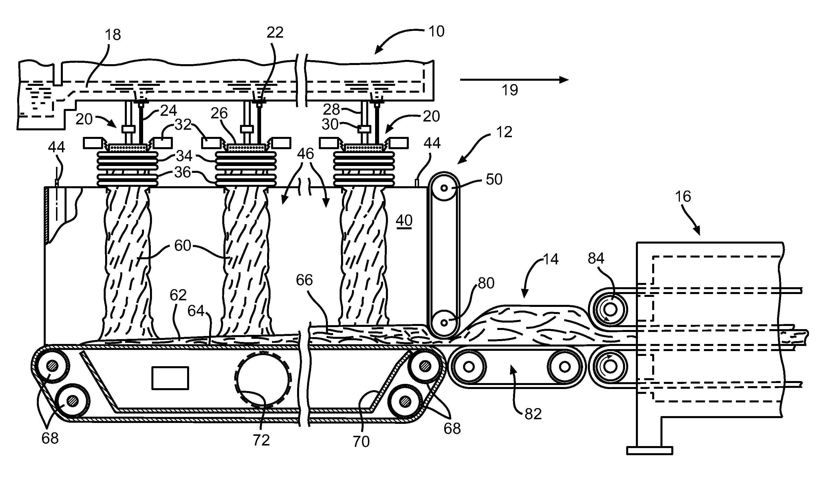
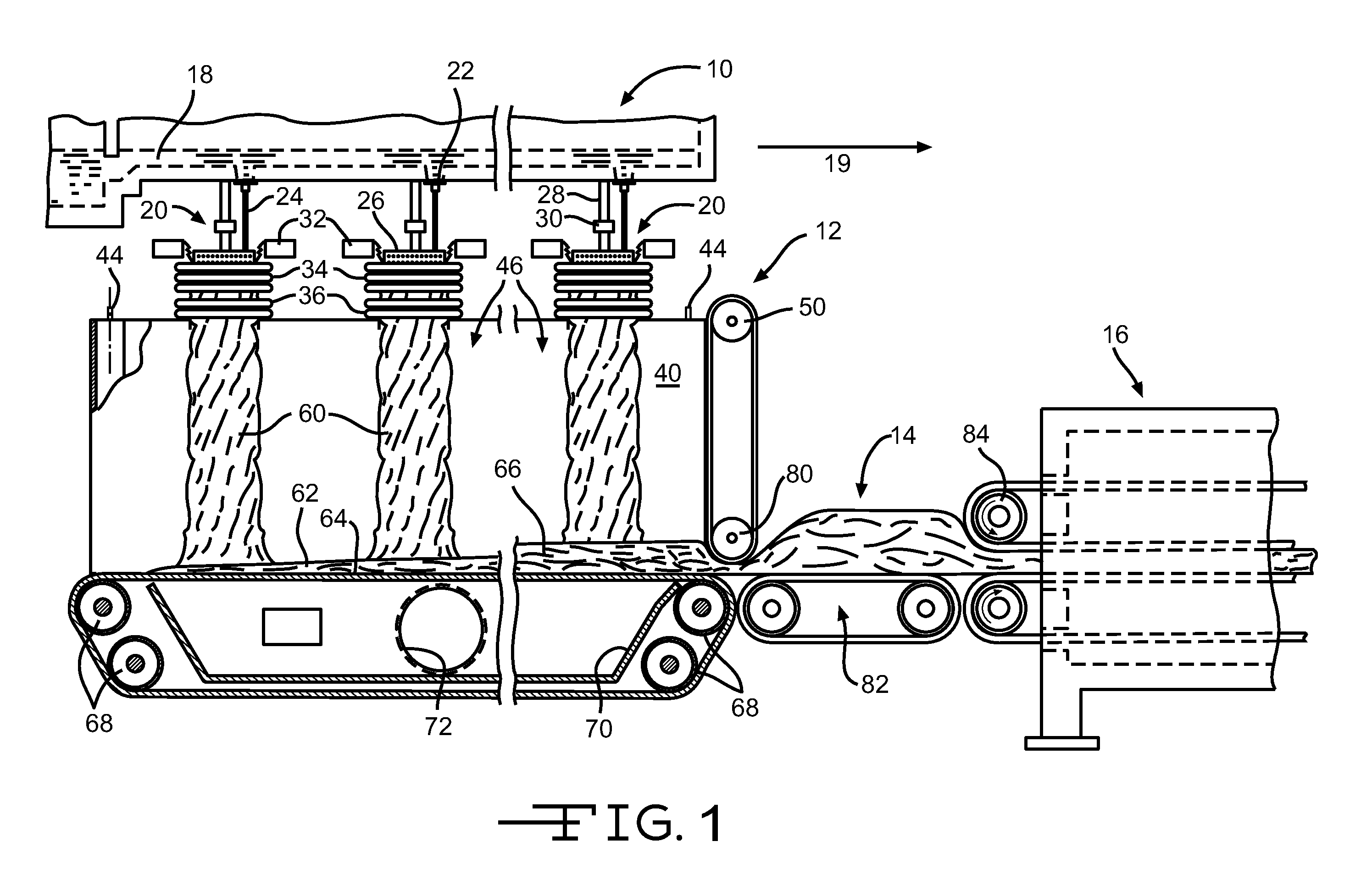
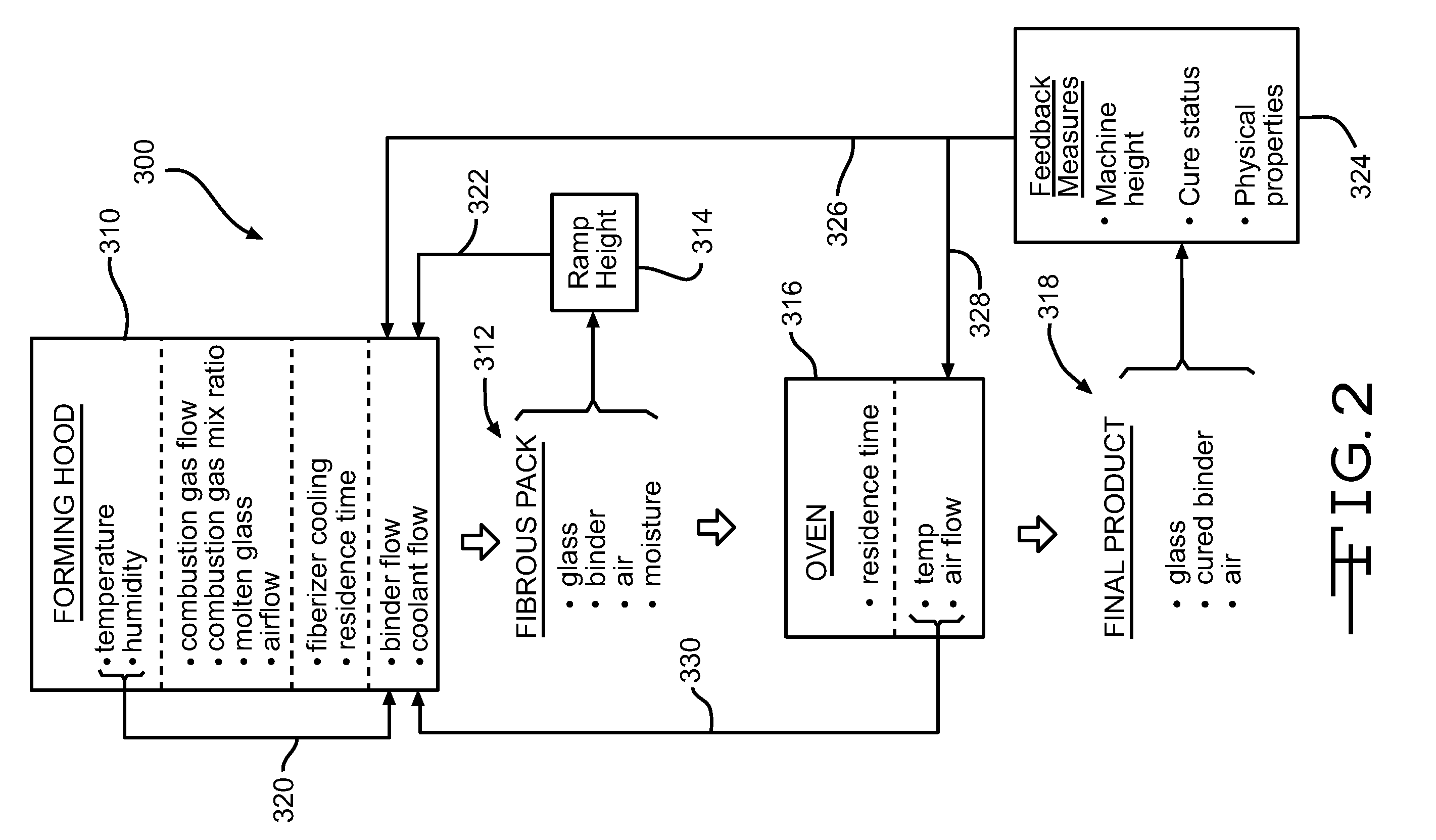
  • Apparatus and method for controlling moisture in the manufacture of glass fiber insulation
  • Apparatus and method for controlling moisture in the manufacture of glass fiber insulation
  • Apparatus and method for controlling moisture in the manufacture of glass fiber insulation

Examples


example 1

[0164]Trials are conducted with varying amounts of water delivered to each of 10 fiberizing units. Ten set points or examples were designed according to Table 1, below. Liquids enter the forming hood as binder dispersion, as diluent for the binder dispersion, or as coolant water, the level of each being varied or held constant as shown in Table 1. Set points 1 and 9 were designed as controls with decreasing or profiled diluent and coolant water at lower average levels to represent the current state of the art. Other set points held various sources of water constant or flat at higher average levels, while others were varied or profiled from one unit to the next. Flows are given in liters per minute, LPM.

TABLE 1Flow* set points for liquids control (as designed**)Fiber.Unit:SetPtLiquids12345678910TOTAL1binder777777777770diluent3.83.83.53.12.31.71.200019.4coolant6.576.85.64.53.52.31.91.51.140.7total fl.17.317.817.315.713.812.210.58.98.58.1130.1bind + dil10.810.810.510.19.38.78.277789.4C...

example 2

[0168]It was found that there were important relationships between several of the variables presented in Table 2. For example, it was discovered that the product properties of vertical weight distribution (VWD), also understood as the vertical density distribution, recovery measures and stiffness measures all improved dramatically with increased thickness of the pack as it exits the forming area and regains its uncompressed state, i.e. the “ramp height.”

[0169]Insulation batts having R-values of R12 and R20 were prepared in standard commercial operations. Quality control data was examined from these manufacturing runs to obtain values for EOL recovery and stiffness / sag at varying run times. Production data was mined to obtain ramp height and these ramp heights were paired to respective product properties for each selected run time. It was found that both recovery and stiffness / sag exhibited correlation to ramp height for both R12 and R20 batts. FIGS. 6B and 6C depict this relationshi...

example 3

[0171]Trials were also run to determine the impact of relative amounts of binder flow and coolant water flow. Set points called for binder flows of 4, 5, and 6 LPM, with binder concentrations being adjusted for equal delivery of binder chemical (same solids / same LOI content). Flow of coolant water was varied and ramp height was monitored. For each binder flow level (4, 5, or 6 LPM), the minimum and maximum ramp heights were about the same, roughly 250 mm for the minimum and 450 mm for the maximum. But at each different binder flow (4, 5, or 6 LPM) it took a different level of coolant flow to achieve the same ramp height levels. As expected, when the binder flow went down, the level of coolant flow had to be increased to achieve comparable ramp heights. Thus, ramp height is related to the total water provided to the forming hood.


PUM

PropertyMeasurementUnit
Fractionaaaaaaaaaa
Fractionaaaaaaaaaa
Fractionaaaaaaaaaa

Abstract

Apparatus, systems and methods for monitoring and controlling the amount of moisture introduced into the forming hood area in the manufacture of mineral fiber insulation products. Moisture from coolant liquids, binder dispersions and binder diluents are all introduced deliberately into a forming hood; ambient moisture and water from combustion are additional sources. A series of global variable control valves, one for each fluid system; as well as individual variable control valves for each fiberizing unit are provided with associated meters. Sensors monitor fibrous pack conditions and ambient conditions and provide inputs to the valve control system. A specific 3-ring liquid dispensing system is also disclosed.

Description

CROSS-REFERENCE TO RELATED APPLICATIONS[0001]This application claims priority to U. S. provisional application Ser. No. 61 / 421,306, filed Dec. 9, 2010, the entire contents of which is incorporated herein by reference. Also incorporated herein in their entireties are U.S. provisional applications bearing Ser. Nos. 61 / 421,301, and 61 / 421,304, and 61 / 421,310, all filed Dec. 9, 2010.BACKGROUND[0002]This invention relates in general to insulation products made from mineral fibers such as fibrous glass and, in particular, to methods and apparatus for controlling product properties by monitoring and controlling moisture in a forming hood.[0003]Fibrous glass insulation products generally comprise randomly-oriented glass fibers bonded together by a cured thermosetting polymeric material. Molten streams of glass are drawn into fibers of random lengths and blown into a forming chamber or hood where they are randomly deposited as a pack onto a moving conveyor or chain. The fibers, while in tran...

Claims


Application Information

Patent Timeline
IPC IPC(8): D04H1/645C03C25/26C03B37/02C03B37/07
CPCC03B37/10C03C25/26D04H13/008D10B2101/06D04H1/4226C03B37/0206D04H1/642D04H1/655B05B7/0892
Inventor MIRTH, DAVID R.GEIGER, STEVEBLACKWOOD, SCOTTINGLIS, FRANK BRUCEBURN, TERRY
Owner OWENS CORNING INTELLECTUAL CAPITAL LLC
Learn More